Eureka AIR delivers breakthrough ideas for toughest innovation challenges, trusted by R&D personnel around the world.

Automobile air conditioner system

An automotive air-conditioning system and air-conditioning housing technology, applied in vehicle components, air handling equipment, lighting and heating equipment, etc., can solve problems such as turbulent flow, icing on the surface of the evaporator core, abnormal air conditioning, etc., and achieve stable wind pressure. , Improve heating and cooling capacity, prevent surface icing effect

Inactive Publication Date: 2017-01-18
BONAIRE AUTOMOTIVE ELECTRICAL SYST
View PDF5 Cites 0 Cited by
  • Summary
  • Abstract
  • Description
  • Claims
  • Application Information

AI Technical Summary

Problems solved by technology

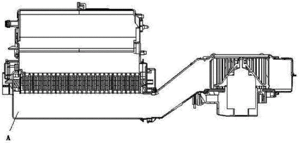
[0002] Automobile air conditioner HVAC structure such as figure 2 As shown, the air intake of the evaporator is blown by the blower and then enters the evaporator by side blowing, so that the wind is likely to cause turbulence at A in the warm air shell, so that the wind on one side of the evaporator is large and the wind on the other half is small; Uneven distribution of air volume causes icing on the surface of the evaporator core, resulting in abnormalities in the air conditioner

Method used


Image

  • Automobile air conditioner system
  • Automobile air conditioner system

Examples


Embodiment Construction

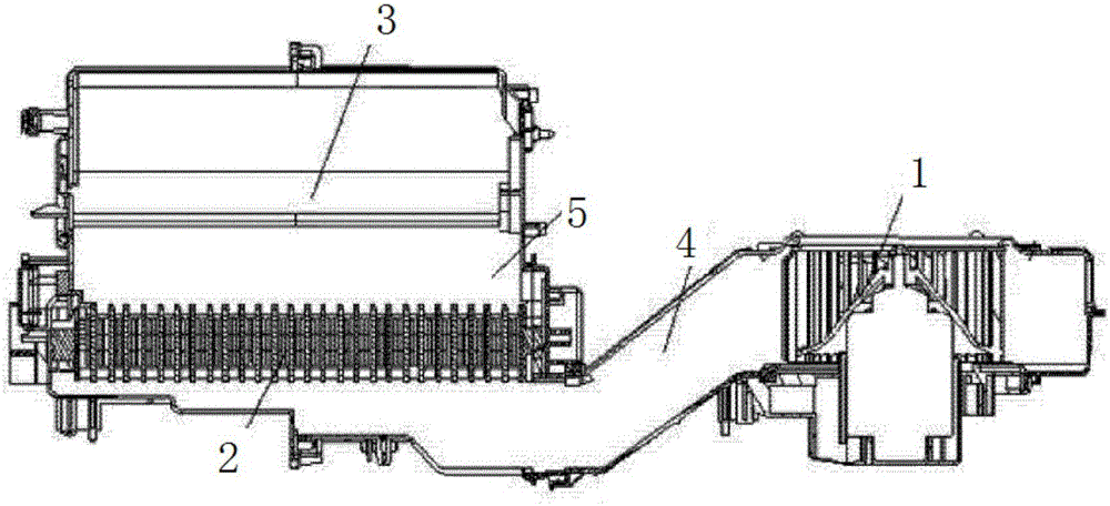
[0013] Such as figure 1 A car air-conditioning system shown includes an air-conditioning housing, and a blower 1, an evaporator core 2, and a heater core 3 arranged in the air-conditioning housing. The air flow channel 4 is connected, and the shell below the evaporator core 2 is in a stepped structure. The guide air duct 4 forms a stepped air duct. An air outlet channel 5 is provided between the evaporator core body 3 and the heater core body 3 . The heater core 3 communicates with the air outlet of the air conditioner housing.

[0014] The air volume entering the evaporator core is evenly distributed and the wind pressure is stable, which is beneficial to prevent the surface of the evaporator core from freezing, and the uniform air volume distribution improves the heating and cooling capacity of the system to meet customer requirements.

[0015] The wind passes through the blower to the diversion air duct, and enters the step-shaped air inlet section below the evaporator ...


PUM


Abstract

The invention discloses an automobile air conditioner system. The automobile air conditioner system comprises an air conditioner casing, an air blower, an evaporator core and a heater core, wherein the air blower, the evaporator core and the heater core are arranged in the air conditioner casing; the air blower and the evaporator core are communicated by a flow guide air passage; the casing under the evaporator core is of a step-shaped structure. The automobile air conditioner system has the advantages that 1, the volume of air entering the evaporator core is uniformly distributed, the air pressure is stable, and the icing on the surface of the evaporator core is favorably prevented; because the volume of air is uniformly distributed, the heating and refrigeration capabilities of the system are improved, and the requirements of a customer are met.

Description

technical field [0001] The invention relates to the technical field of automobile air conditioning, in particular to an automobile air conditioning system. Background technique [0002] Automobile air conditioner HVAC structure such as figure 2 As shown, the air intake mode of the evaporator is blown by the blower and then enters the evaporator by side blowing, so that the wind will easily cause turbulent flow at A in the warm air shell, so that the wind on one side of the evaporator is large and the wind on the other half is small; because Uneven distribution of air volume causes icing on the surface of the evaporator core, resulting in abnormalities in the air conditioner. Contents of the invention [0003] The technical problem to be solved by the present invention is to provide an automobile air-conditioning system that avoids icing on the surface of the evaporator core body in view of the deficiencies in the prior art. [0004] In order to solve the above-mentioned ...

Claims


Application Information

Patent Timeline
IPC IPC(8): B60H1/00F25B39/02
CPCB60H1/00035B60H1/00021B60H2001/00092F25B39/02F25B2339/02
Inventor 田小梅周红霞潘帮斌
Owner BONAIRE AUTOMOTIVE ELECTRICAL SYST
Why Eureka
Eureka Blog
Learn More