Rectifier circuit with bandpass characteristics and wide input power range
A technology of rectification circuit and band-pass characteristics, which is applied in the field of microwave energy transmission systems, can solve the problems of widening the input power range and realizing band-pass characteristics, and achieves the effect of high-efficiency rectification
- Summary
- Abstract
- Description
- Claims
- Application Information
AI Technical Summary
Problems solved by technology
Method used
Image
Examples
Embodiment 1
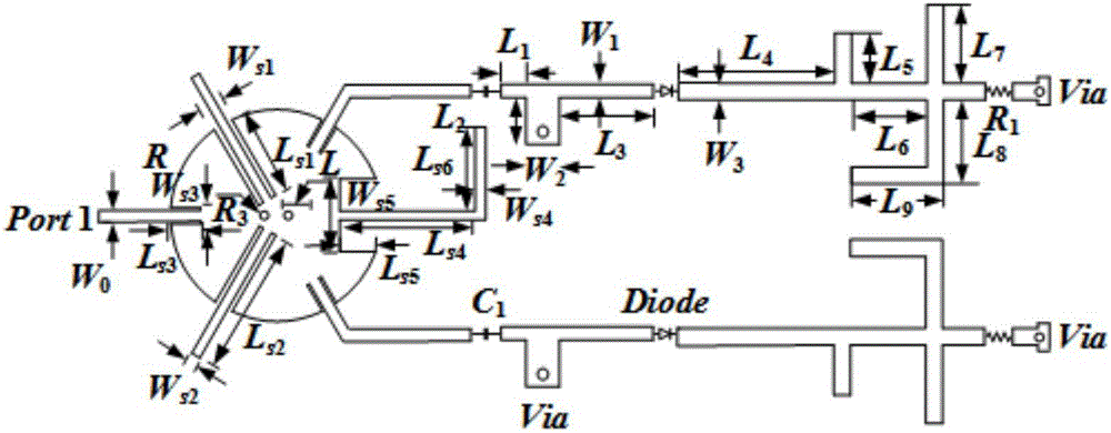
[0041] Such as figure 1 As shown, the rectification circuit includes a power divider with bandpass characteristics and two sub-rectification circuits connected with the power divider, wherein the sub-rectification circuits include a matching circuit, a rectifier diode, a DC filter and an impedance load, and the two sub-rectification circuits of the matching circuit The terminals are respectively connected to the power divider and the anode of the rectifier diode, the cathode of the rectifier diode is connected to the DC filter, and the DC filter is connected to the impedance load.
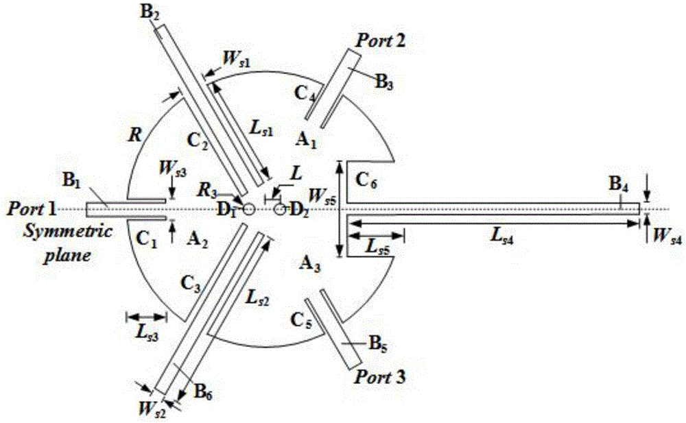
[0042] Among them, such as figure 2As shown, the power splitter includes a circular patch, impedance matching line B2, impedance matching line B4, impedance matching line B6, port line B1, port line B3 and port line B5, the radius of the circular patch is R, and the circular Slot C2, slot C3, slot C6, slot C1, slot C4 and slot C5 are respectively opened on the patch along its radial direction, be...
Embodiment 2
[0049] In this embodiment, on the basis of the rectifier circuit provided in Embodiment 1, a specific simulation experiment is carried out, and the parameters used in the experiment are as follows:
[0050] Power splitter working parameters at 2.45GHz: W 0 = 1.38, R = 12.9, R 3 = 0.5, W s1 = 2.4, L s1 =11.2, W s2 = 1.7, L s2 = 17.7, W s3 = 2.2, L s3 = 3.7, W s4 = 1.1, L s4 = 15.6, L s6 = 10.5, W s5 = 8.8, L s5 = 5.1, L = 1.5.
[0051] Working parameters of sub rectifier circuit at 2.45GHz: C 1 =5pF, R 1 =1200Ω, L 1 = 3, L 2 = 5.9, L 3 =11.6, L 4 = 19, L 5 = 5.8, L 6 = 9, L 7 = 9, L 8 = 10.1, L 9 = 8.8, W 1 = 1.6, W 2 =3.9, W 3 = 2.2.
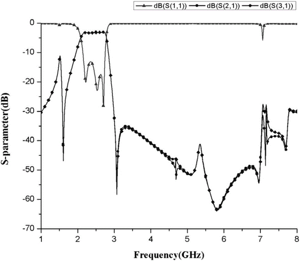
[0052] The specific experimental results are as Figure 3~7 as shown,
[0053] Such as image 3 As shown, the rectifier circuit can suppress the third harmonic at 2.45GHz.
[0054] Such as Figure 4 As shown, the center frequency of the rectifier circuit with ba...
PUM
 Abstract
Description
Claims
Application Information
 - Generate Ideas
- Intellectual Property
- Life Sciences
- Materials
- Tech Scout
- Unparalleled Data Quality
- Higher Quality Content
- 60% Fewer Hallucinations
Browse by: Latest US Patents, China's latest patents, Technical Efficacy Thesaurus, Application Domain, Technology Topic, Popular Technical Reports.
© 2025 PatSnap. All rights reserved.Legal|Privacy policy|Modern Slavery Act Transparency Statement|Sitemap|About US| Contact US: help@patsnap.com


