
DC power supply apparatus

A technology of DC power supply and timing device, which is applied in the direction of output power conversion device, electrical components, DC power input conversion to DC power output, etc. It can solve the problems of current detection part loss, low conversion efficiency of power loss, low conversion efficiency, etc. , to achieve the effect of improving conversion efficiency and efficient synchronous rectification

Inactive Publication Date: 2009-02-04
SANKEN ELECTRIC CO LTD
View PDF7 Cites 0 Cited by
  • Summary
  • Abstract
  • Description
  • Claims
  • Application Information

AI Technical Summary

Problems solved by technology

Therefore, for example, by using a current detection unit provided in the secondary side circuit to detect the current flowing from the transformer into the rectification switching element on the secondary side, when the current stops flowing, the rectification switching element can be turned off immediately, However, in this case, there is a problem that a loss occurs in the current detection part, and the conversion efficiency is low.
In particular, in the current resonance type switching power supply of Patent Document 1, since a choke coil is inserted into the secondary side circuit through which a large current flows, the size of the device is increased, and the conversion efficiency due to power loss in the choke coil low problem

Method used


Image

  • DC power supply apparatus
  • DC power supply apparatus
  • DC power supply apparatus

Examples


Embodiment Construction

[0042] Refer to Figure 1- Figure 19 Seven embodiments of the DC power supply device of the present invention will be described. In Figure 1~ Figure 19 among, with Figure 20 Parts that are substantially the same at the positions shown are given the same reference numerals and their explanations are omitted.

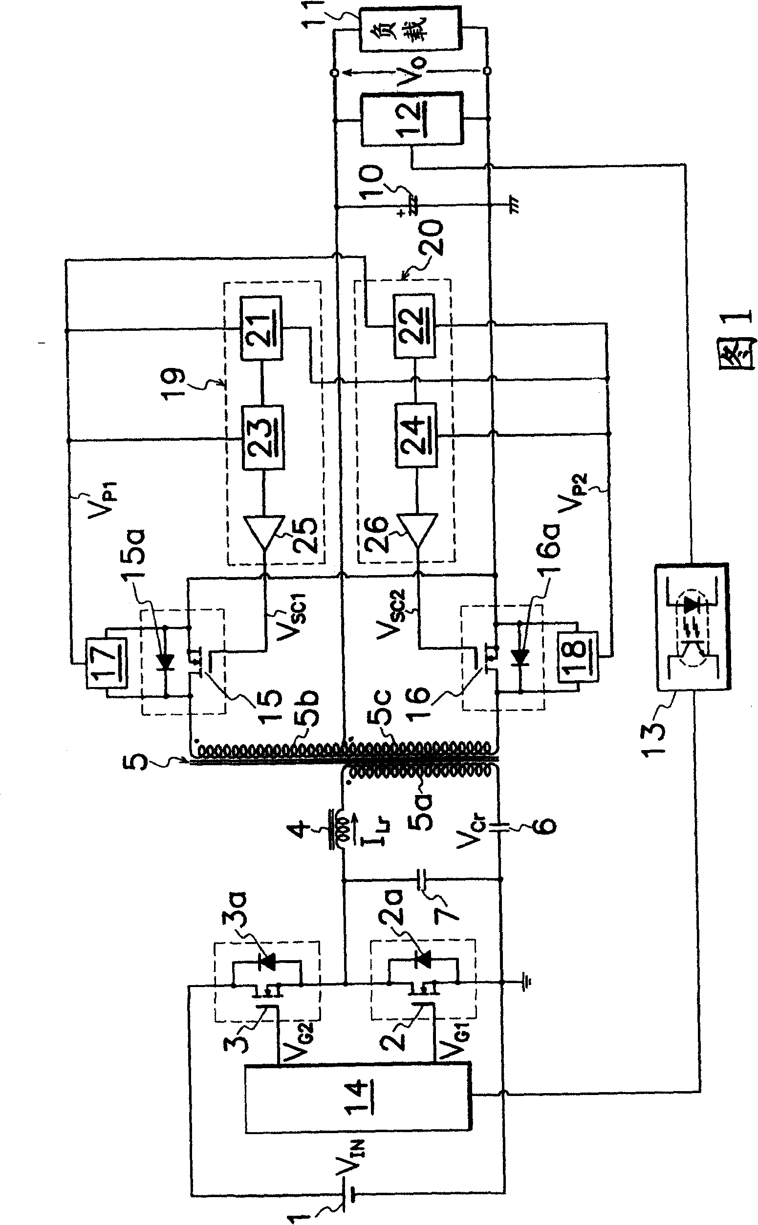
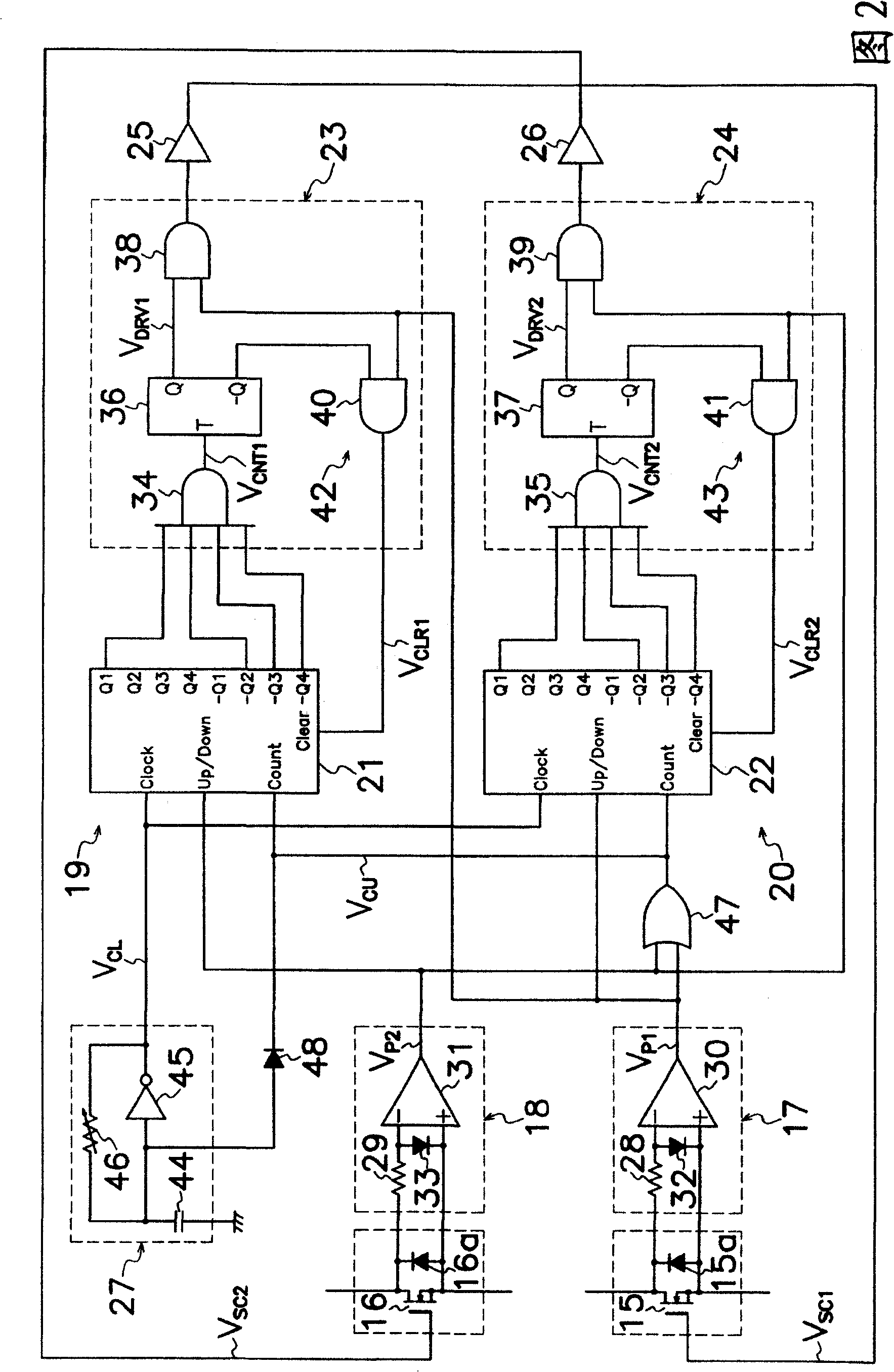
[0043] The DC power supply device according to the first embodiment of the present invention shown in FIG. 1 is a Figure 20 The pair of rectifier diodes (8, 9) of the current DC power supply device shown are changed to rectification MOS-FETs (15, 16) as rectification switching elements, and a conduction detection device as a polarity detection device is also provided. A circuit (17, 18) that outputs a conduction detection signal V when a current flows in the rectifying MOS-FET (15, 16). P1 , V P2 and as the timing circuit (19,20) of the timing device, the detection signal V of the conduction detection circuit (17,18) before the current flowing in the rectification M...


PUM


Abstract

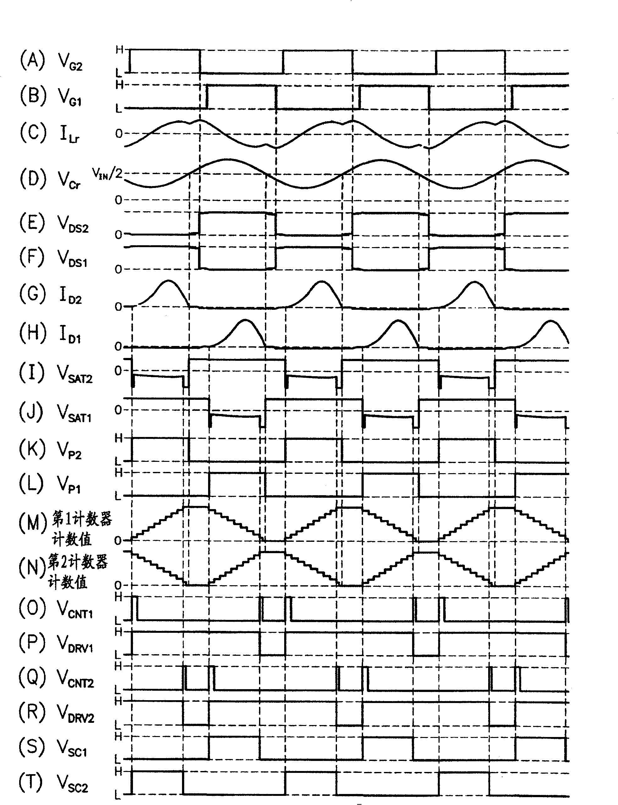
The DC power supply of the invention is provided with conduction detecting circuits (17, 18) for outputting detected signals VP1, VP2during the conduction of rectifying MOS-FETs (15, 16), and timing circuits (19, 20) connected to the conduction detecting circuits (17, 18). The timing circuits (19, 20) measure the output periods of the detected signals VP1, VP2from the conduction detecting circuits (17, 18), until a current ID1flowing in the rectifying MOS-FET (15) becomes zero, turn off the rectifying MOS-FET (16) at a time, immediately before the measured period is ended, and surely turn off the rectifying MOS-FETs (15, 16) within a conduction period of a rectifying circuit. Accordingly, efficient and synchronous rectification can be conducted.

Description

technical field [0001] The invention relates to a DC power supply device such as a switching power supply, in particular to a DC power supply device capable of efficiently performing synchronous rectification. Background technique [0002] The DC power supply device of the current resonance type (SMZ method) is well known as a DC power supply device with high efficiency and low switching noise. For example, Figure 20 The present current resonant DC power supply unit shown has: [0003] The main MOS-FETs (2, 3) are connected in series to the DC power supply (1) as a pair of switching elements; [0004] A circuit and a voltage resonance capacitor (7) are connected in series, a resonance reactance (4) connected in parallel with one main MOS-FET (2), a primary winding (5a) of a transformer (5), and a current resonance capacitor ( 6); [0005] The first secondary winding (5b) of the transformer (5); [0006] the second secondary winding (5c), which has the same number of tur...

Claims


Application Information

Patent Timeline
Patent Type & Authority Patents(China)
IPC IPC(8): H02M3/28
CPCY02B70/1475H02M3/33592Y02B70/10H02M3/28
Inventor 京野羊一
Owner SANKEN ELECTRIC CO LTD
Learn More