
A dielectric isolation structure and method for SOI process

A dielectric isolation and process technology, applied in electrical components, transistors, circuits, etc., can solve the problems that the shallow trench isolation technology cannot meet the circuit requirements, high complexity, and the difficulty of the full dielectric isolation process, so as to improve the resistance to total dose radiation. Lighting ability, small impact, avoid long-term high temperature annealing effect

Active Publication Date: 2019-12-06
58TH RES INST OF CETC
View PDF4 Cites 0 Cited by
  • Summary
  • Abstract
  • Description
  • Claims
  • Application Information

AI Technical Summary

Problems solved by technology

However, for the SOI process with thick silicon film, the full dielectric isolation process between devices is difficult and complex, and the shallow trench isolation technology cannot meet the circuit requirements

Method used


Image

  • A dielectric isolation structure and method for SOI process
  • A dielectric isolation structure and method for SOI process
  • A dielectric isolation structure and method for SOI process

Examples


Embodiment Construction

[0040] Below in conjunction with accompanying drawing and embodiment, describe technical solution of the present invention in detail:

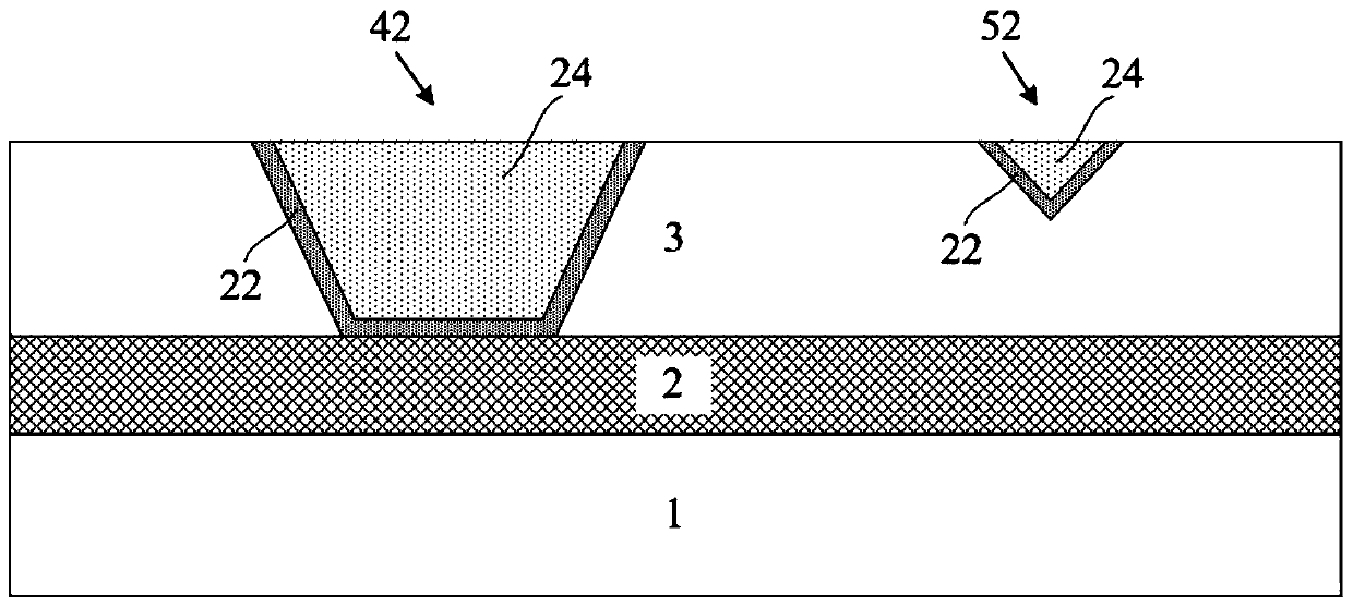
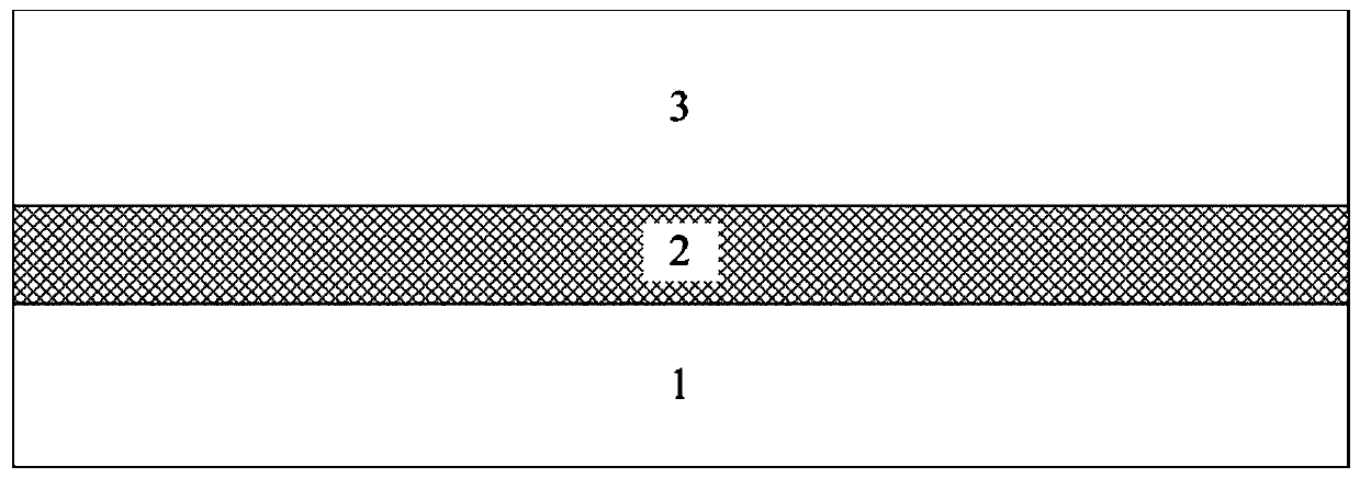
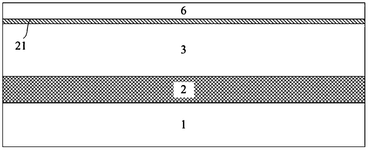
[0041] Such as figure 1 As shown, a dielectric isolation structure for SOI process of the present invention includes a P-type substrate 1, a buried oxide layer 2, an SOI material top layer silicon 3, a full dielectric isolation trench 42, a partial dielectric isolation trench 52, and a linear oxide layer 22. The oxide layer 24, the full dielectric isolation trench 42 and part of the dielectric isolation trench 52 are located in the top layer silicon 3 of the SOI material, above the buried oxide layer 2, the linear oxide layer 22 is located between the full dielectric isolation trench 42 and part of the dielectric isolation trench 52 On the inner surface, the oxide layer 24 is surrounded by the linear oxide layer 22 and is located inside the full dielectric isolation trench 42 and part of the dielectric isolation trench 52 , while the linear ox...


PUM


Abstract

The invention relates to a dielectric isolation structure and a dielectric isolation method for an SOI technology. The isolation structure comprises a P-type substrate, a buried oxide layer, SOI material top silicon, a full dielectric isolation trench, a partial dielectric isolation trench, a linear oxide layer, and an oxide layer or an oxide insulation layer. The full dielectric isolation trench and the partial dielectric isolation trench are disposed inside the SOI material top silicon and above the buried oxide layer. The linear oxide layer is disposed on the inner surfaces of the full dielectric isolation trench and the partial dielectric isolation trench. The oxide layer or the oxide insulation layer is surrounded by the linear oxide layer, and is disposed inside the full dielectric isolation trench and the partial dielectric isolation trench. The linear oxide layer is disposed between the isolation trenches and the SOI material top silicon. The radiation resistance of an integrated circuit is improved. Moreover, the complexity and difficulty of the SOI full dielectric isolation process of a thick silicon film under the process condition of big line width are reduced, the field region and the full-dielectric isolation region are formed at the first attempt, and a smooth silicon surface is ensured.

Description

technical field [0001] The invention belongs to the technical field of integrated circuits, and relates to a dielectric isolation structure used in SOI technology and a method thereof. Background technique [0002] SOI (Silicon-On-Insulator) technology, as a full-dielectric isolation technology, effectively overcomes the shortage of bulk silicon materials with its unique structure, and fully exploits the potential of silicon integrated circuit technology. Power consumption, high integration and high reliability VLSI mainstream technology. SOI technology adopts full dielectric isolation, which completely eliminates the parasitic latch effect of CMOS devices, reduces single event flipping interfaces, and has excellent anti-single event and instantaneous radiation capabilities, enabling SOI chips to work in the harshest cosmic ray environment , are widely used in space science. However, the charge trapping and interface states generated by the total dose ionization damage in ...

Claims


Application Information

Patent Timeline
Patent Type & Authority Patents(China)
IPC IPC(8): H01L27/092H01L21/8238H01L21/762
CPCH01L21/7624H01L21/823878H01L27/092
Inventor 李燕妃朱少立吴建伟洪根深
Owner 58TH RES INST OF CETC
Learn More