
shaft assembly

A technology of shaft assembly and assembly, applied in the direction of bearing elements, shafts, crankshafts, etc., can solve the problems of time-consuming, expensive surface, etc.

Active Publication Date: 2021-02-26
FORD GLOBAL TECH LLC
View PDF1 Cites 0 Cited by
  • Summary
  • Abstract
  • Description
  • Claims
  • Application Information

AI Technical Summary

Problems solved by technology

Producing such precisely machined surfaces is expensive and time-consuming

Method used


Image

  • shaft assembly
  • shaft assembly
  • shaft assembly

Examples


Embodiment Construction

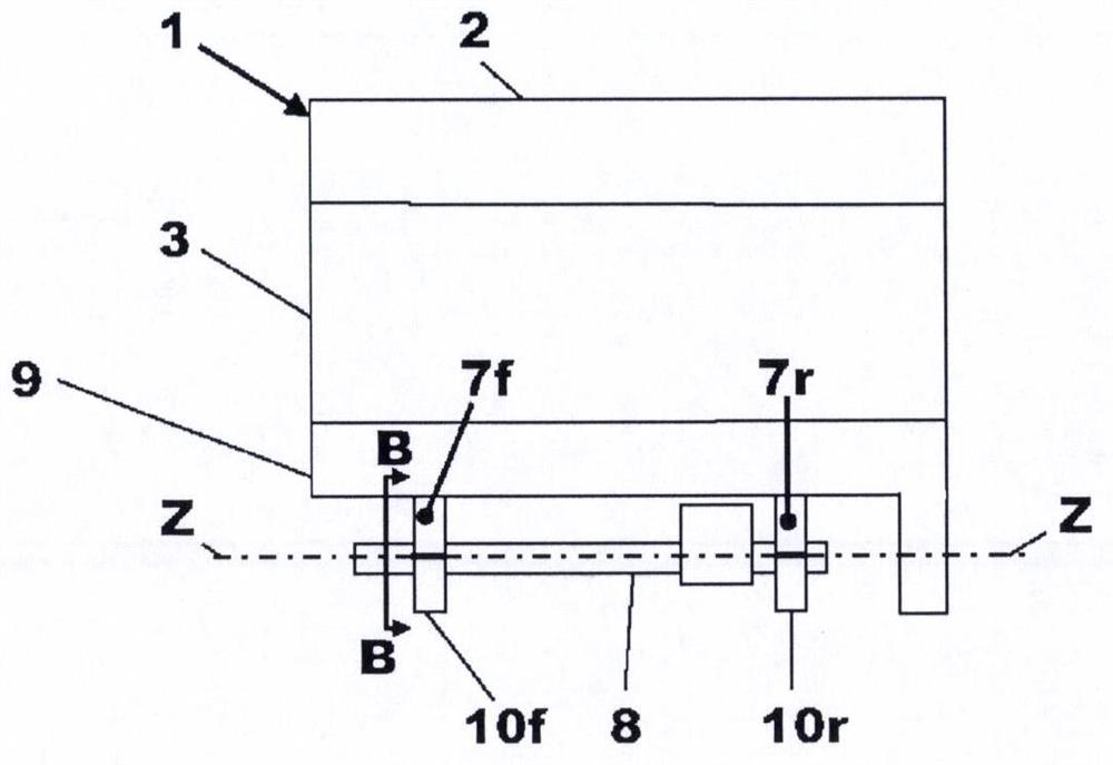
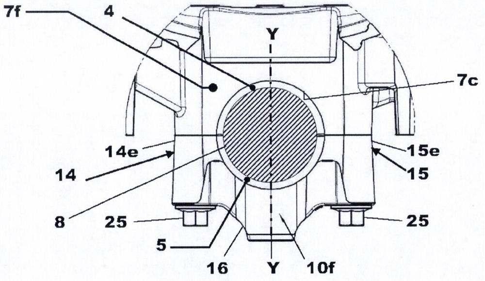
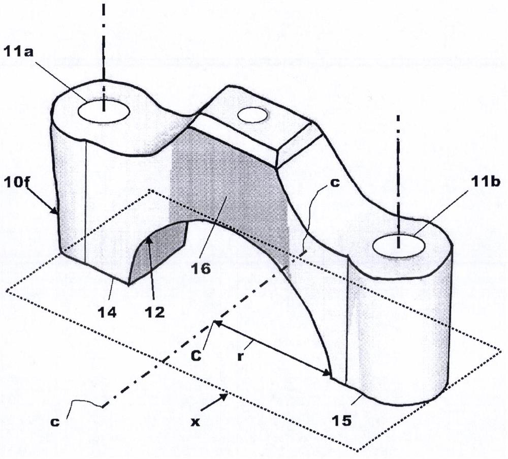
[0046] specific reference Figure 1a , Figure 1b , figure 2 with image 3 , shows an engine 1 having a cylinder head 2 , a cylinder block 3 and a trapezoidal frame 9 bolted to the lower end of the cylinder block 3 . The trapezoidal frame 9 defines at the lower end a front bearing support structure 7f and a rear bearing support structure 7r, to each of which a respective error proof bearing cap 10f, 10r is bolted by a pair of bolts 25 . The front bearing cap 10f is bolted to the front bearing support structure 7f and the rear bearing cap 10r is bolted to the rear bearing support structure 7r.

[0047] In the exemplary case where the shaft 8 is an engine balancer shaft, the shaft 8 is rotatably supported by the front bearing cap 10f and the rear bearing cap 10r and the front bearing support structure 7f and the rear bearing support structure 7r to form a shaft and bearing assembly. In the example case, the shaft 8 is rotatably supported by two bearing support assemblies 7f,...


PUM


Abstract

The present application discloses a shaft assembly that may include two or more yaw-proof bearing caps, each having a pair of reference holes that are offset from a central axis of the bearing caps by different offset distances. The bearing cap defines a semicircular recess positioned so that, in use, the central axis of the semicylindrical recess in the bearing cap is aligned with the axis of rotation of a shaft rotatably supported by the bearing cap . The different offset of the reference holes prevents the bearing caps from being assembled in reverse orientation. To ensure that each bearing cap can only be fitted in one position, the center-to-center spacing between the first and second reference holes of each bearing cap differs from the center-to-center spacing of other bearing caps used to support a single shaft.

Description

[0001] related application [0002] This application claims priority to UK Patent Application No. 1511413.5 filed 30 June 2015, which is hereby incorporated by reference in its entirety for all purposes. technical field [0003] The present invention relates to rotatably supporting shafts, and in particular to Poka-Yoke bearing caps forming part of a shaft assembly. Background technique [0004] It is known to support a shaft using a split bearing support having two parts defining a bore in which the shaft is rotatably supported. [0005] Assemblies of rotating shafts require split bearing supports with bores that provide very good positional tolerances, cylindricity and concentricity, regardless of the type of bearing used. [0006] The required accuracy is best met if the split bearing support is drilled straight together, ie all concentric holes are machined in one operation with all parts in place. [0007] In order to meet the functional requirements, it is important ...

Claims


Application Information

Patent Timeline
Patent Type & Authority Patents(China)
IPC IPC(8): F02F7/00F01L1/047F16C3/035F16C3/06
CPCF01L1/047F02F7/0021F02F7/006F02F7/0073F02F7/0082F02F7/0095F16C3/035F16C3/06F16C35/02F16C35/10F16C2326/06F16C35/047F16C35/12F01L2001/0476F02F7/0053F02F7/00F16C9/02
Inventor X·德默勒纳尔M·米歇尔
Owner FORD GLOBAL TECH LLC
Learn More