Method and device for testing rock mass strength through technology of monitoring during drilling

A rock mass strength, while drilling technology, applied in the direction of using stable tension/pressure to test material strength, measuring device, strength characteristics, etc., can solve the problem of not being able to give mechanical parameters such as elastic modulus and strength of different formations, etc. Achieve fast and accurate results

Active Publication Date: 2017-01-11
INST OF MECHANICS - CHINESE ACAD OF SCI
View PDF5 Cites 24 Cited by
  • Summary
  • Abstract
  • Description
  • Claims
  • Application Information

AI Technical Summary

Problems solved by technology

Although such methods can distinguish strata of different lithologies through differences in electromag...

Method used


Image

  • Method and device for testing rock mass strength through technology of monitoring during drilling
  • Method and device for testing rock mass strength through technology of monitoring during drilling

Examples


Embodiment 1

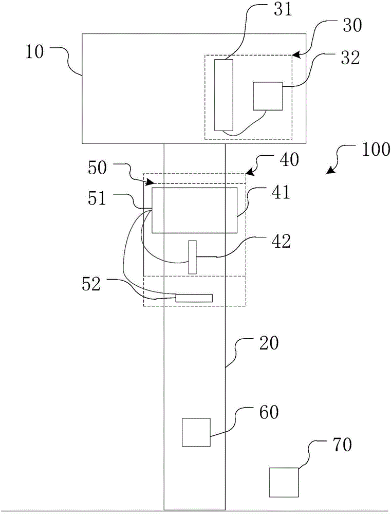
[0057] The strength of the rock mass was tested using the monitoring-while-drilling technology. The selected area was the platform behind the air-face in blasting mining. The distance from the drill hole to the air-face was 9m. The formation in this area was mainly limestone. The produced YZ35D roller cone drilling rig is drilling. When the previous drilling is completed, the rotary trolley is at the bottom to install the monitoring equipment.

[0058] Install the laser range finder and wireless transmitter on the rotary trolley. During the installation process, ensure the verticality between the laser range finder and the ground; paste the strain gauge on the drill pipe to test the axial pressure and torque of the drill pipe. The strain gauge adopts full Bridge connection, and connected with the INV3062T0 24-bit network synchronous acquisition instrument produced by Beijing Dongfang Vibration and Noise Technology Research Institute. Record the rotational speed by counting lap...

Embodiment 2

[0063] The strength of the rock mass was tested using the monitoring-while-drilling technology. The selected area was the platform behind the air face of blasting mining. The distance from the drill hole to the air face was 9m. The stratum in this area was mainly iron ore. The YZ35D roller cone drilling rig produced by the company is drilling. When the previous drilling is completed, the rotary trolley is at the bottom to install the monitoring equipment.

[0064] Install the laser range finder and wireless transmitter on the rotary trolley. During the installation process, ensure the verticality between the laser range finder and the ground; paste the strain gauge on the drill pipe to test the axial pressure and torque of the drill pipe. The strain gauge adopts full Bridge connection, and connected with the INV3062T0 24-bit network synchronous acquisition instrument produced by Beijing Dongfang Vibration and Noise Technology Research Institute. Record the rotational speed by ...


PUM

PropertyMeasurementUnit
Cohesionaaaaaaaaaa
Cohesionaaaaaaaaaa
Cohesionaaaaaaaaaa

Abstract

The invention provides a method and device for testing rock mass strength through the technology of monitoring during drilling. The method includes the steps that firstly, various measuring devices are installed on a rotary drilling rig; secondly, the rotary drilling rig is leveled; thirdly, a drilling experiment is conducted in an experimental field to obtain corresponding relationships between parameters of a drill pipe under different lithologic characters; fourthly, an indoor rock mechanic experiment is conducted to obtain rock mass strength parameters at different depths; fifthly, the function relationship between the rock mass strength parameters and the drill pipe is constructed; sixthly, according to the strength parameters, a computational formula capable of calculating the rock mass strengt at drilling positions according to work parameters of a drilling machine can be obtained; seventhly, testing during drilling is carried out in a testing area, and the rock mass strength parameters at different drilling depths are quickly obtained through the computational formula. By researching the quantitative relationship of shaft pressure of the drill pipe, torque of the drill pipe, rotation speed, drilling speed and rock mass strength, the aim of quickly and accurately obtaining the rock mass strength in the drilling process can be achieved. Compared with a traditional method, the method is simple and easy to implement.

Description

technical field [0001] The invention belongs to the technical field of mining and rock and soil mechanics, and in particular relates to a method for testing rock mass strength parameters and a device using the method. Background technique [0002] The mechanical properties of the rock mass are closely related to the drillability and blastability of the rock mass. It is not only the basis for the rational design of blasting parameters, but also the main index to evaluate the difficulty of subsequent mechanical breaking of this type of rock mass. Existing methods for testing the mechanical properties of rock mass generally include drilling and coring methods, stress wave methods, and electromagnetic methods. [0003] The drilling coring method is to obtain rock samples by drilling, and then make the rock samples into test pieces, and test the mechanical properties of the test pieces through test equipment. Due to the complexity of the stratum distribution, it is difficult to ...

Claims


Application Information

Patent Timeline
IPC IPC(8): E21B49/00G01N3/08
CPCE21B49/003G01N3/08G01N2203/0019
Inventor 李世海冯春郭汝坤乔继延郑炳旭李战军崔晓荣
Owner INST OF MECHANICS - CHINESE ACAD OF SCI
Why Eureka
Try Eureka