
Rotary distributing axial impact drilling tool

A technology of axial impact and drilling tools, which is applied to drilling equipment, driving devices for drilling in boreholes, and earthwork drilling and mining, etc. It can solve the problems of reducing the service life of the valve body, affecting the service life of tools, and small impact energy. Achieve the effect of reducing drilling cost, increasing ROP and shortening drilling cycle

Active Publication Date: 2017-01-11
CHINA UNIV OF PETROLEUM (BEIJING) +1
View PDF6 Cites 7 Cited by
  • Summary
  • Abstract
  • Description
  • Claims
  • Application Information

AI Technical Summary

Problems solved by technology

Although this technology has been applied to a certain extent, the use effect is not good. From the perspective of on-site use, the main problems include: 1) the service life of the tool cannot meet the on-site demand; 2) the structure of some tools is relatively complicated, and the stability not enough
The jet cavity mainly changes the movement direction of the jet through the change of the internal pressure of the cavity. When the jet occurs, due to the high-speed movement of the drilling fluid and there are many solid particles in the drilling fluid, when this method is adopted, the impact on the jet channel Corrosion is more serious, affecting the service life of the tool
The valve-type percussion drilling tool mainly realizes the reversing of the movement of the impact part through the axial reciprocating movement of the valve body structure. Impact action, which will seriously reduce the service life of the valve body
When the valve body changes the direction of fluid movement, it changes the direction suddenly. This sudden change will affect the stability of the valve body when it is working, which is not conducive to the stability of the tool.
However, when the oscillating cavity is used, due to its structural characteristics, the impact energy generated by it is small, which cannot meet the needs of rock breaking in hard formations.

Method used


Image

  • Rotary distributing axial impact drilling tool
  • Rotary distributing axial impact drilling tool
  • Rotary distributing axial impact drilling tool

Examples


Embodiment Construction

[0046] In order to have a clearer understanding of the technical features, purposes and effects of the present invention, the specific implementation manners of the present invention will now be described with reference to the accompanying drawings.

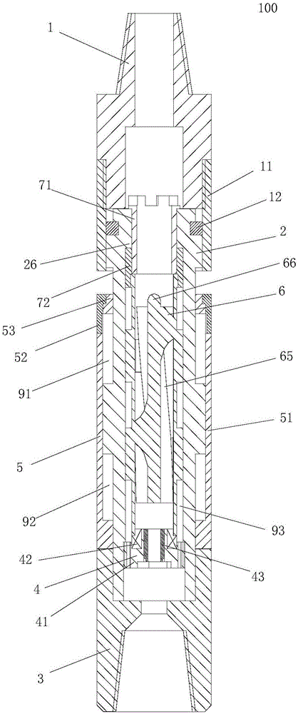
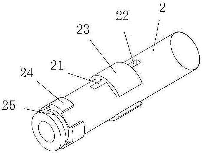
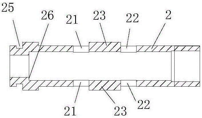
[0047] Such as figure 1 As shown, the present invention proposes a rotary flow distribution type axial percussion drilling tool 100. The rotary flow distribution type axial percussion drilling tool 100 includes an upper joint 1 that penetrates up and down. The lower end of the upper joint 1 is axially fixedly connected to a support that penetrates up and down. Tube 2, the outer wall of the bottom end of the support tube 2 is fixedly connected to a drill seat 3, and the inner wall of the lower part of the support tube 2 is fixedly provided with a rotating support 4 that penetrates up and down, and the outer wall of the support tube 2 above the drill seat 3 slides axially. A cylindrical hammer 5 is provided, and the outer wall of t...


PUM


Abstract

The invention discloses a rotary distributing axial impact drilling tool which comprises an upper joint. A supporting cylinder is axially fixed at the lower end of the upper joint, a drill bit seat is fixed at the bottom end of the supporting cylinder, a rotary support is fixedly arranged on the inner wall of the lower portion of the supporting cylinder, a cylindrical punch hammer is axially and slidably arranged on the outer wall of the supporting cylinder, an upper cavity and a lower cavity are hermetically formed between the supporting cylinder and the cylindrical punch hammer, an upper through hole and a lower through hole are respectively formed in the wall of the supporting cylinder and communicated with the upper cavity and the lower cavity, a turbine rotor drum with the bottom supported on the rotary support is axially arranged inside the supporting cylinder, turbine blades are arranged on the inner wall of the turbine rotor drum, a first sector through hole and a second sector through hole are formed in the outer wall of the turbine rotor drum and axially correspond to the upper through hole and the lower through hole respectively, and the first sector through hole and the second sector through hole are alternately communicated with the upper through hole and the lower through hole in rotation of the turbine rotor drum. The rotary distributing axial impact drilling tool is simple and reliable in structure, impact frequency and impact power can be increased, and rock breaking efficiency is improved.

Description

technical field [0001] The invention relates to a downhole drilling tool in the field of oil development, in particular to a rotary distribution type axial percussion drilling tool. Background technique [0002] The improvement of ROP in hard formation has always been a difficult problem in drilling engineering. The crushing of hard strata per unit volume requires a large amount of energy. At present, the conventional drilling technology is rotary drilling technology. The rock is broken by the rotation of the drill pipe driven by the drill bit, and the pressure (weight on bit) of the drill bit on the rock is realized by the self-weight of the drill pipe. This pressure makes the drill bit eat into the inside of the rock. However, this kind of pressure is static pressure, and its crushing efficiency to rocks in hard formations is low. [0003] Experiments have proved that percussion drilling technology is an effective method to improve the ROP in hard formations. This techn...

Claims


Application Information

Patent Timeline
IPC IPC(8): E21B4/16E21B4/02
CPCE21B4/02E21B4/16
Inventor 柳贡慧查春青李军席岩姜海龙
Owner CHINA UNIV OF PETROLEUM (BEIJING)
Learn More