
A pile foundation permeable breakwater taking into account the function of power generation

A technology of breakwaters and pile foundations, applied in breakwaters, hydropower, hydropower stations, etc., can solve the problem of poor reliability of parts affecting harbor basins and open sea water, sediment exchange, wave energy capture and conversion, and less functional design considerations, etc. problems, to achieve the effect that is conducive to social promotion, considerable comprehensive effect, and low construction difficulty

Active Publication Date: 2019-07-23
ZHEJIANG UNIV
View PDF5 Cites 0 Cited by
  • Summary
  • Abstract
  • Description
  • Claims
  • Application Information

AI Technical Summary

Problems solved by technology

[0004] Among the published or authorized patents, in terms of breakwater design, most of the disclosed technical solutions focus on the improvement of the structure of the breakwater, and only focus on the blocking and weakening of the breakwater itself on waves. For the combination of breakwater design and wave energy utilization In terms of wave energy utilization in offshore areas, most of the published technical solutions only focus on the conversion and utilization of wave energy, and less consideration is given to the functional design of wave blocking and wave dissipation; while considering wave energy utilization and breakwater construction at the same time In the combined technical schemes, the reliability of wave energy capture and conversion is poor to varying degrees, the construction of breakwaters affects the exchange of water and sediment between the harbor basin and the open sea, the construction speed is slow under sea conditions, and the construction cost is relatively high. question

Method used


Image

  • A pile foundation permeable breakwater taking into account the function of power generation
  • A pile foundation permeable breakwater taking into account the function of power generation
  • A pile foundation permeable breakwater taking into account the function of power generation

Examples


Embodiment Construction

[0034] In order to describe the present invention more specifically, the technical solutions of the present invention will be described in detail below in conjunction with the accompanying drawings and specific embodiments.

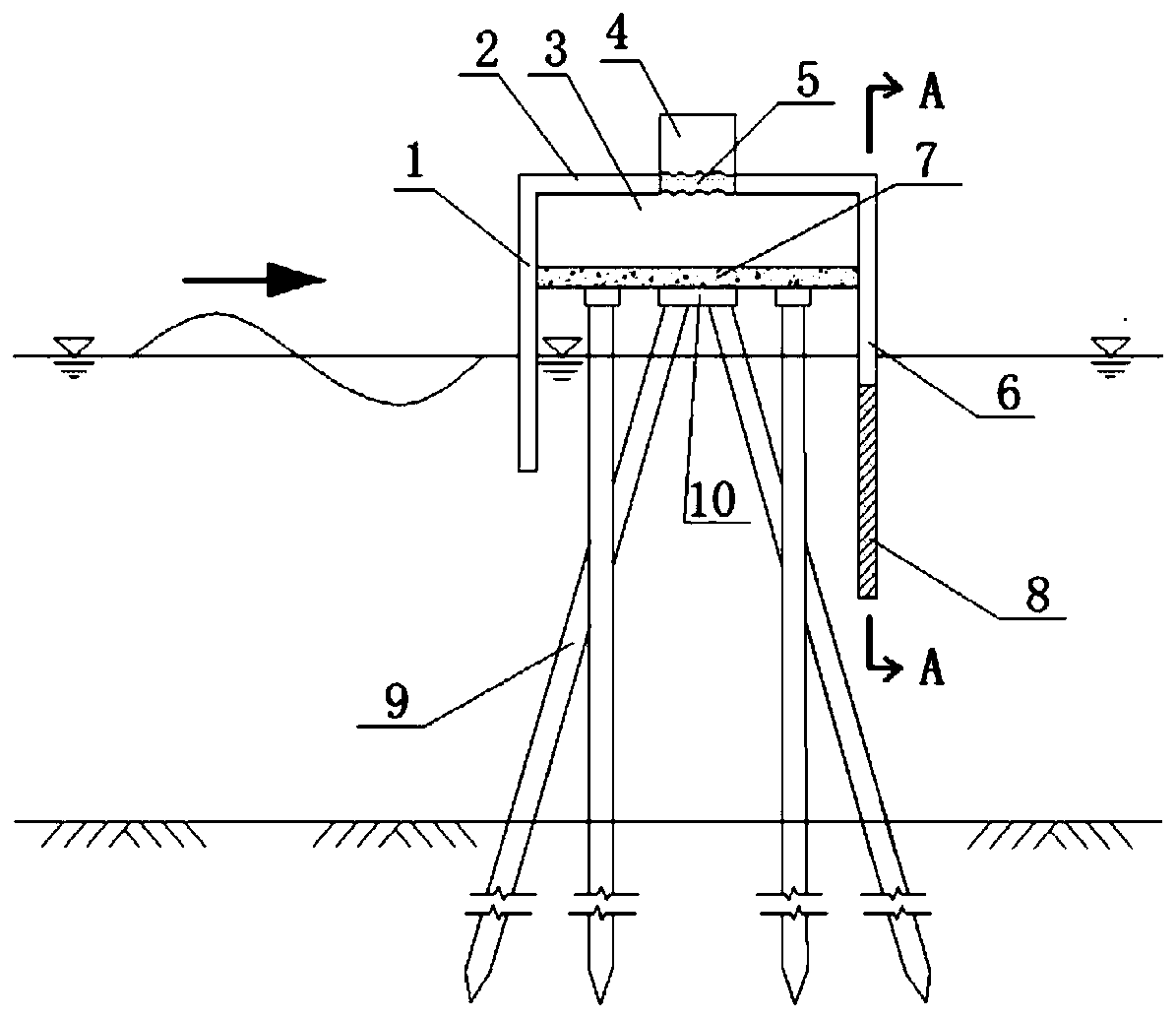
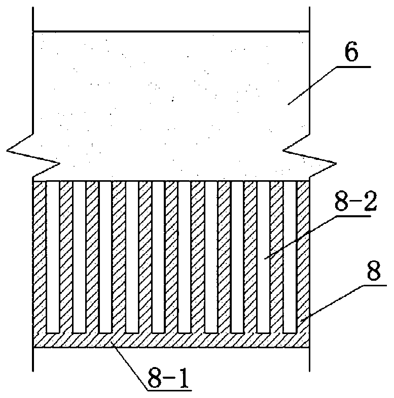
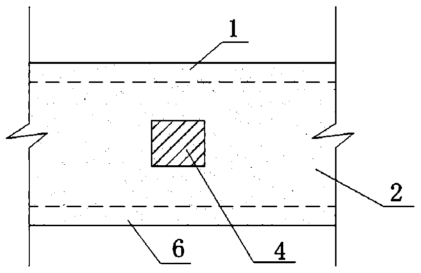
[0035] A pile-based permeable breakwater taking into account the function of power generation, such as figure 1 As shown, it is composed of air chamber front wall 1, air chamber roof 2, air chamber 3, generator set 4, air turbine 5, air chamber rear wall 6, beam 7, wave baffle 8, foundation pile 9 and pile cap 10, The front wall 1 of the air chamber is located on the facing wave side; the air chamber top plate 2 is provided with an airflow channel, and the air turbine 5 is installed at the airflow passage; the generator set 4 is connected to the air turbine 5 through mechanical transmission; the wave baffle 8 is located in the air chamber The bottom of the rear wall 6 is vertically connected with the rear wall 6 of the air chamber; the foundation pile 9 s...


PUM


Abstract

The invention discloses a pile foundation permeable bulwark integrating the power generation function and an achieving method, and belongs to the field of bulwarks. The pile foundation permeable bulwark comprises an air chamber, an air turbine, a power generator set, a wave baffle, a beam and a pile foundation. The air chamber is composed of an air chamber front wall, an air chamber top plate and an air chamber rear wall. The air chamber front wall is located on the wave facing side. The air chamber top plate is provided with an airflow channel. The air turbine and the power generator set are arranged in the airflow channel. The wave baffle is located below the air chamber rear wall. The beam is arranged between the pile foundation and the air chamber. Under the premise that the bulwark plays an original wave stopping and eliminating role, the wave energy power generation function is integrated, composite function utilization of traditional buildings is achieved, and environment friendliness is achieved. Meanwhile, the pile foundation permeable design is adopted in the bulwark, exchange of water inside and outside a port is allowed, and environment friendliness is obvious.

Description

technical field [0001] The invention belongs to a breakwater, in particular to a pile foundation air-through breakwater which takes into account the power generation function. Background technique [0002] Since the beginning of the 21st century, the use of traditional energy has led to increasing environmental pollution. The development and utilization of clean energy is imminent, especially the development and utilization of clean renewable energy has become the focus of people's attention. As a high-quality marine renewable energy, wave energy has gradually entered people's sight. Wave energy has the advantages of green, clean, wide distribution and huge content. Nowadays, people have designed and manufactured many wave energy capture and utilization devices. Among them, the wave energy utilization method with relatively mature design, industrial operation and high reliability is to use the wave energy conversion principle of oscillating water column for wave energy conve...

Claims


Application Information

Patent Timeline
Patent Type & Authority Patents(China)
IPC IPC(8): E02B3/06E02B9/00E02D27/14
CPCE02B3/06E02B9/00E02D27/14Y02E10/20
Inventor 何方冷杰
Owner ZHEJIANG UNIV
Learn More