
Barrier combination structure and method for ditch water treatment and debris flow protection

A ditch water treatment and combined structure technology, applied in water conservancy projects, coastline protection, water conservancy engineering equipment, etc., can solve problems such as low safety of retaining dams, impact of retaining dams, blockage of drainage holes, etc., to achieve overall construction convenience and avoid hazards. , the effect of easy dismantling and refurbishment

Active Publication Date: 2019-01-11
CHINA HYDROELECTRIC ENGINEERING CONSULTING GROUP CHENGDU RESEARCH HYDROELECTRIC INVESTIGATION DESIGN AND INSTITUTE
View PDF8 Cites 0 Cited by
  • Summary
  • Abstract
  • Description
  • Claims
  • Application Information

AI Technical Summary

Problems solved by technology

However, due to the impact of heavy rain or other natural disasters, some valleys are prone to debris flow disasters. The debris flow can block the drainage holes and cause poor drainage. The debris flow will also cause a certain impact on the retaining dam, making the safety of the retaining dam lower.
Therefore, conventional ditch water treatment measures are difficult to meet the needs of engineering construction. It is necessary to study a water conservancy and hydropower engineering structure that can not only effectively block and treat perennial flowing water, but also resist the hazards of debris flow.

Method used


Image

  • Barrier combination structure and method for ditch water treatment and debris flow protection
  • Barrier combination structure and method for ditch water treatment and debris flow protection
  • Barrier combination structure and method for ditch water treatment and debris flow protection

Examples


Embodiment Construction

[0020] The present invention will be further described below in conjunction with the accompanying drawings and specific embodiments.

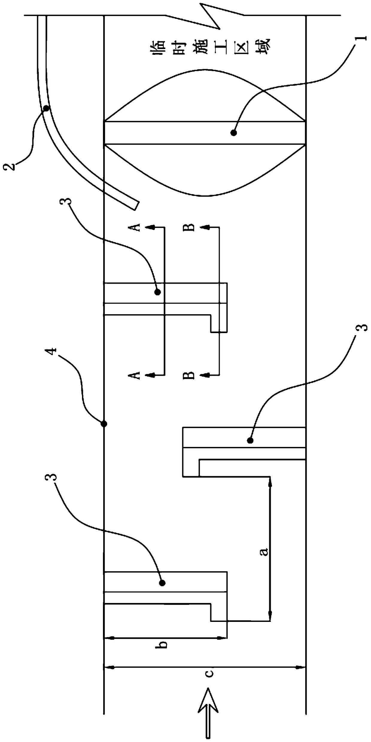
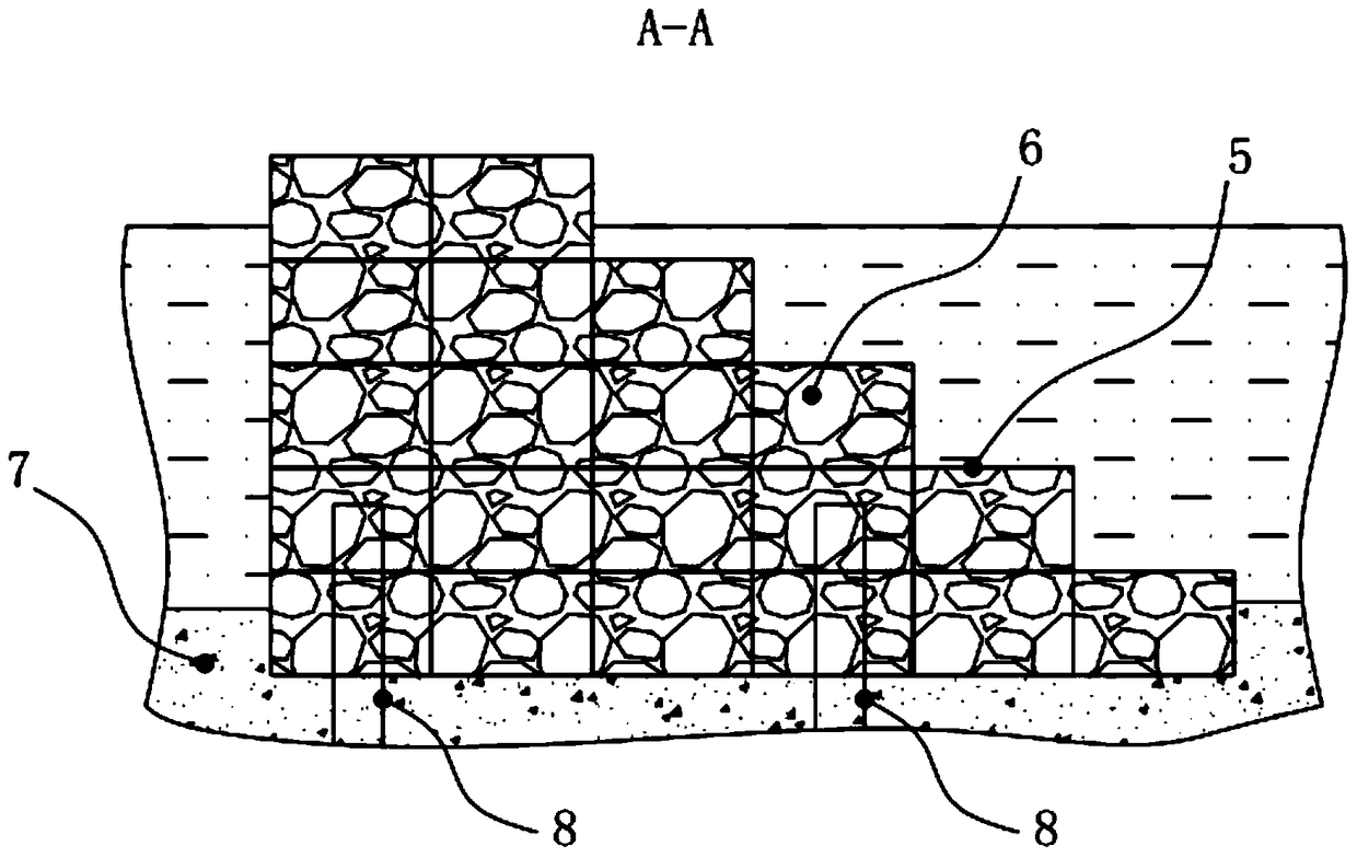
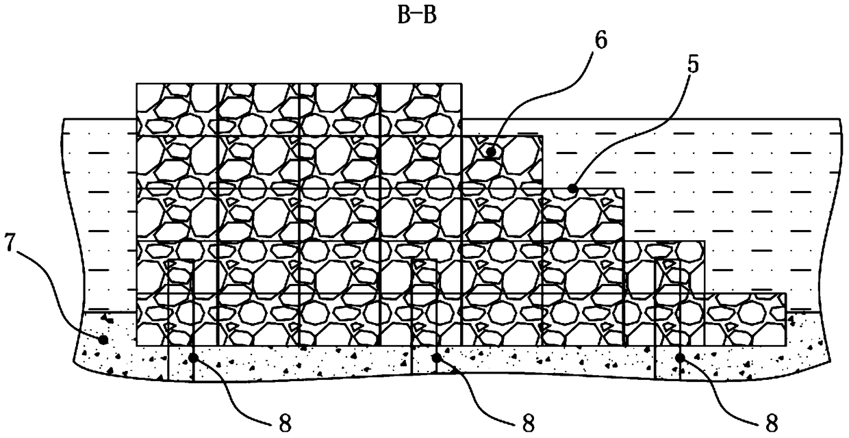
[0021] Such as Figure 1 to Figure 4 As shown in the present invention, the retaining composite structure for ditch water treatment and debris flow protection includes a retaining dam 1 and a drainage hole 2 that communicates the upstream channel of the retaining dam 1 with the downstream channel; it also includes an intercepting dam 3, the The intercepting dam 3 is located upstream of the retaining dam 1, one end of the intercepting dam 3 is connected to the edge 4 of the river channel, and the other end extends into the channel. The function of retaining dam 1 and drainage tunnel 2 is to block the river in the valley and provide a temporary construction area for the downstream; and the function of interception dam 3 is to intercept the solid matter in the river and realize the flow of solid water at the same time. For example, when debris fl...


PUM


Abstract

The invention provides a blocking composite structure and method for gully water treatment and debris flow protection, which can effectively treat all-year-round running water of gullies and resist debris flow, and belongs to the field of water conservancy and hydropower constructions. The blocking composite structure comprises a water retaining dam and a drainage tunnel making an upstream riverway of the water retaining dam communicate with a downstream riverway, and further comprises an intercepting dam which is located on the upstream side of the water retaining dam. One end of the intercepting dam is connected with the edge of the riverway and the other end extends into the riverway. While the water retaining dam and the drainage tunnel are arranged, the intercepting dam is arranged on the upstream side of the water retaining dam, so that the blocking composite structure can perform effective blocking and drainage treatment on all-year-round running water of gullies, provide a temporary construction area for a downstream area, resist special natural disasters such as debris flow and prevent the damage to the water retaining dam caused by debris flow.

Description

technical field [0001] The invention relates to the field of water conservancy and hydropower structures, in particular to a barrier combination structure for ditch water treatment and debris flow protection for tributary valleys in alpine and canyon areas, and a barrier method using the barrier combination structure. Background technique [0002] When building a hydropower station in an alpine valley area, the tributary valleys are mostly full of perennial water and are cut deeply. There are very few construction sites near the dam area, and a large amount of construction waste needs to be piled up during the project construction, and various arrangements need to be made. Therefore, the tributary valleys near the dam site are often used as ditch-blocking spoil sites, construction auxiliary facilities areas, etc., and the valleys need to be treated with ditch water. The conventional ditch water treatment method mostly adopts the method of retaining dam + drainage tunnel, and...

Claims


Application Information

Patent Timeline
Patent Type & Authority Patents(China)
IPC IPC(8): E02B1/00E02B7/02
Inventor 张超
Owner CHINA HYDROELECTRIC ENGINEERING CONSULTING GROUP CHENGDU RESEARCH HYDROELECTRIC INVESTIGATION DESIGN AND INSTITUTE
Learn More