


Quick Research
Generate reliable direction feasibility study reports for your R&D in just a few steps.

Technical Q&A
Discover and master advanced knowledge NOW. Basics, ideas, possibilities, all at once.

Find Solutions
As an expert in R&D theories, this can generate solutions to your technical problems instantly.

Evaluate Feasibility
Analyze your overall solution with one click, know your potential R&D risks in advance.

Monitor Landscape
Get weekly tech updates, stay abreast of the latest tech innovations and key insights.
A horn bracket magnetic bowl glue injection drying device
A technology of a horn bracket and a drying device, which is applied to sensors, electrical components, etc., can solve the problems of poor drying effect, low work efficiency and high production cost, and achieve the effect of good drying effect, high work efficiency and low production cost.
- Summary
- Abstract
- Description
- Claims
- Application Information
AI Technical Summary
Problems solved by technology
Method used
Image

Examples
Embodiment 1
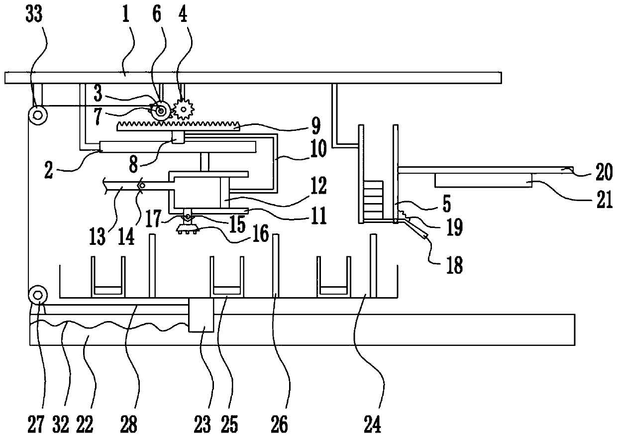
[0031] A horn bracket magnetic bowl glue injection drying device, such as figure 1As shown, it includes a top plate 1, a first slide rail 2, a reduction motor 3, a first gear 4, a placement box 5, a second gear 6, a winding wheel 7, a first slider 8, a rack 9, and a connecting rod 10 , Glue spray box 11, push plate 12, liquid inlet pipe 13, first one-way valve 14, liquid outlet pipe 15, nozzle 16, second one-way valve 17, rotating plate 18, first spring 19, mounting plate 20, UV lamp 21, second slide rail 22, second slide block 23, mobile box 24, placement frame 25, stop bar 26, first roller 27, stay wire 28, second spring 32 and second roller 33, top board 1 bottom from From left to right, the second roller 33, the first slide rail 2, the reduction motor 3, the first gear 4 and the placement box 5 are arranged successively. The front side of the reduction motor 3 is provided with the second gear 6, and the second gear 6 and the first gear 4 meshing, the front side of the sec...
Embodiment 2
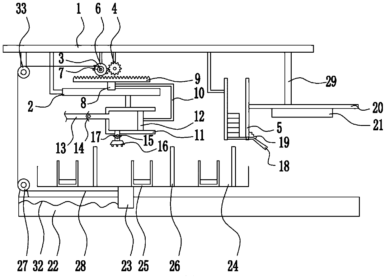
[0033] A horn bracket magnetic bowl glue injection drying device, such as figure 2 As shown, it includes a top plate 1, a first slide rail 2, a reduction motor 3, a first gear 4, a placement box 5, a second gear 6, a winding wheel 7, a first slider 8, a rack 9, and a connecting rod 10 , Glue spray box 11, push plate 12, liquid inlet pipe 13, first one-way valve 14, liquid outlet pipe 15, nozzle 16, second one-way valve 17, rotating plate 18, first spring 19, mounting plate 20, UV lamp 21, second slide rail 22, second slide block 23, mobile box 24, placement frame 25, stop bar 26, first roller 27, stay wire 28, second spring 32 and second roller 33, top board 1 bottom from From left to right, the second roller 33, the first slide rail 2, the reduction motor 3, the first gear 4 and the placement box 5 are arranged successively. The front side of the reduction motor 3 is provided with the second gear 6, and the second gear 6 and the first gear 4 meshing, the front side of the s...
Embodiment 3
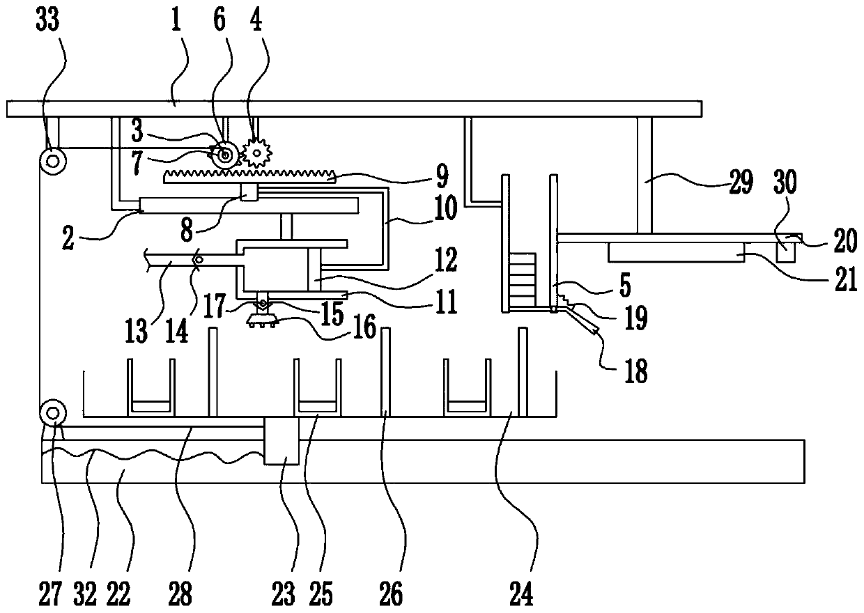
[0036] A horn bracket magnetic bowl glue injection drying device, such as Figure 1-4 As shown, it includes a top plate 1, a first slide rail 2, a reduction motor 3, a first gear 4, a placement box 5, a second gear 6, a winding wheel 7, a first slider 8, a rack 9, and a connecting rod 10 , Glue spray box 11, push plate 12, liquid inlet pipe 13, first one-way valve 14, liquid outlet pipe 15, nozzle 16, second one-way valve 17, rotating plate 18, first spring 19, mounting plate 20, UV lamp 21, second slide rail 22, second slide block 23, mobile box 24, placement frame 25, stop bar 26, first roller 27, stay wire 28, second spring 32 and second roller 33, top board 1 bottom from From left to right, the second roller 33, the first slide rail 2, the reduction motor 3, the first gear 4 and the placement box 5 are arranged successively. The front side of the reduction motor 3 is provided with the second gear 6, and the second gear 6 and the first gear 4 meshing, the front side of the...
PUM
 Abstract
Description
Claims
Application Information
 - R&D Engineer
- R&D Manager
- IP Professional
- Industry Leading Data Capabilities
- Powerful AI technology
- Patent DNA Extraction
Browse by: Latest US Patents, China's latest patents, Technical Efficacy Thesaurus, Application Domain, Technology Topic, Popular Technical Reports.
© 2024 PatSnap. All rights reserved.Legal|Privacy policy|Modern Slavery Act Transparency Statement|Sitemap|About US| Contact US: help@patsnap.com