Detection apparatus based on time domain analysis and detection method thereof

A time-domain analysis and detection device technology, applied in electrical components and other directions, can solve the problems of slow detection efficiency and large calculation amount, and achieve the effect of high detection efficiency and small calculation amount

Pending Publication Date: 2017-01-04
ZILLTEK TECH SHANGHAI +1
View PDF0 Cites 3 Cited by
  • Summary
  • Abstract
  • Description
  • Claims
  • Application Information

AI Technical Summary

Problems solved by technology

Existing microphone distortion detection is performed through the frequency domain. The specific detection method is as follows: the microphone to be detected acquires a voice signal for a period of time. The anti-aliasing band-pass filter takes out the frequency components of the voice signal in the range of 300Hz to 3400Hz, then samples the voice signal at a sampling rate of 8kHz, and continues to perform DTFT (discrete Fouriertransform) function transformation processing, Transform the time-domain sampling signal of the speech signal into the corresponding frequency-domain sampling signal, obtain the frequency-domain signal that matches the speech signal, analyze the frequency-domain signal to obtain its spectrum, and continue to perform low-pass filtering on the spectrum to filter out effective signal, retain its distorted signal, and continue to perform RMS (Root Meam Square) integral processing or sampling and quantization processing on the distorted signal to obtain the processing result, and then analyze the processing result to judge the distortion degree of the microphone, but this detection method has some limitations. Disadvantages, that is, the amount of calculation is large, and Fourier transform is required to obtain frequency domain functions, RMS integration or sampling quantization processing, and the detection efficiency is relatively slow

Method used


Image

  • Detection apparatus based on time domain analysis and detection method thereof
  • Detection apparatus based on time domain analysis and detection method thereof

Examples


Embodiment Construction

[0034] The present invention will be further described below in conjunction with the accompanying drawings and specific embodiments, but not as a limitation of the present invention.

[0035] The following will clearly and completely describe the technical solutions in the embodiments of the present invention with reference to the accompanying drawings in the embodiments of the present invention. Obviously, the described embodiments are only some, not all, embodiments of the present invention. Based on the embodiments of the present invention, all other embodiments obtained by persons of ordinary skill in the art without making creative efforts belong to the protection scope of the present invention.

[0036] It should be noted that, in the case of no conflict, the embodiments of the present invention and the features in the embodiments can be combined with each other.

[0037] The present invention will be further described below in conjunction with the accompanying drawings ...


PUM


Abstract

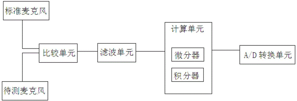
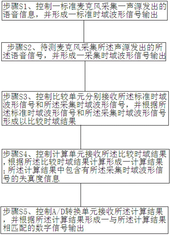
The invention relates to the detection technology field of a signal acquisition device and especially relates to a detection apparatus based on time domain analysis. The apparatus comprises a standard microphone, a microphone to be detected, a comparison unit, a calculating unit and an AD conversion unit. A standard time domain waveform signal and an acquisition time domain waveform signal are acquired respectively. The comparison unit carries out subtraction processing on the standard time domain waveform signal and the acquisition time domain waveform signal so as to acquire a comparison time domain result. The comparison time domain result is formed by a variable and a constant. The calculating unit calculates the comparison time domain result, the constant is removed, the variable is maintained and statistics is performed on a variable portion so that a distortion degree of the variable is acquired. The distortion degree of the variable is a distortion degree of the microphone to be detected. In the invention, collected time domain signals are directly compared, the signals do not need to be converted into frequency domain signals, operand is small and detection efficiency is high. Simultaneously, a position of the microphone to be detected does not need to be arranged deliberately and a detection purpose can be realized under any positions.

Description

technical field [0001] The invention relates to the detection technical field of a signal acquisition device, in particular to a detection device and a detection method based on time domain analysis. Background technique [0002] A microphone, scientifically known as a microphone, is an energy conversion device that converts sound signals into electrical signals. As an important component of voice signal acquisition, in order to improve the performance of the microphone, it is usually necessary to perform distortion detection before the microphone product leaves the factory. Existing microphone distortion detection is performed through the frequency domain. The specific detection method is as follows: the microphone to be detected acquires a voice signal for a period of time. The anti-aliasing band-pass filter takes out the frequency components of the voice signal in the range of 300Hz to 3400Hz, then samples the voice signal at a sampling rate of 8kHz, and continues to per...

Claims


Application Information

Patent Timeline
IPC IPC(8): H04R29/00
Inventor 叶菁华
Owner ZILLTEK TECH SHANGHAI
Why Eureka
Try Eureka