
Combined type multifunctional router

A router and multi-functional technology, applied in the field of combined multi-functional routers, can solve the problems of not having other plane angle adjustment functions, inconvenient to carry and disassemble, and single function of the router, so as to enhance the ability of transmitting and receiving electromagnetic wave signals, Good dustproof function, simple structure effect

Inactive Publication Date: 2017-01-04
成都捷科菲友信息技术有限公司
View PDF0 Cites 1 Cited by
  • Summary
  • Abstract
  • Description
  • Claims
  • Application Information

AI Technical Summary

Problems solved by technology

[0003] The function of the antenna is to transmit and receive electromagnetic wave signals. The antennas equipped with existing wireless routers generally can only rotate in a fixed plane around the installation axis, and do not have other plane angle adjustment functions. Therefore, in order to ensure that the antenna can be in various situations The best angle to meet the wireless router Internet speed and coverage standards, people sometimes have to often move the wireless router body to adjust the angle of the antenna in other planes
And moving the router body often involves the corresponding adjustment of the network cable, which is very inconvenient, and most of the existing routers have single functions, which are not easy to carry and disassemble.

Method used


Image

  • Combined type multifunctional router
  • Combined type multifunctional router
  • Combined type multifunctional router

Examples


Embodiment 1

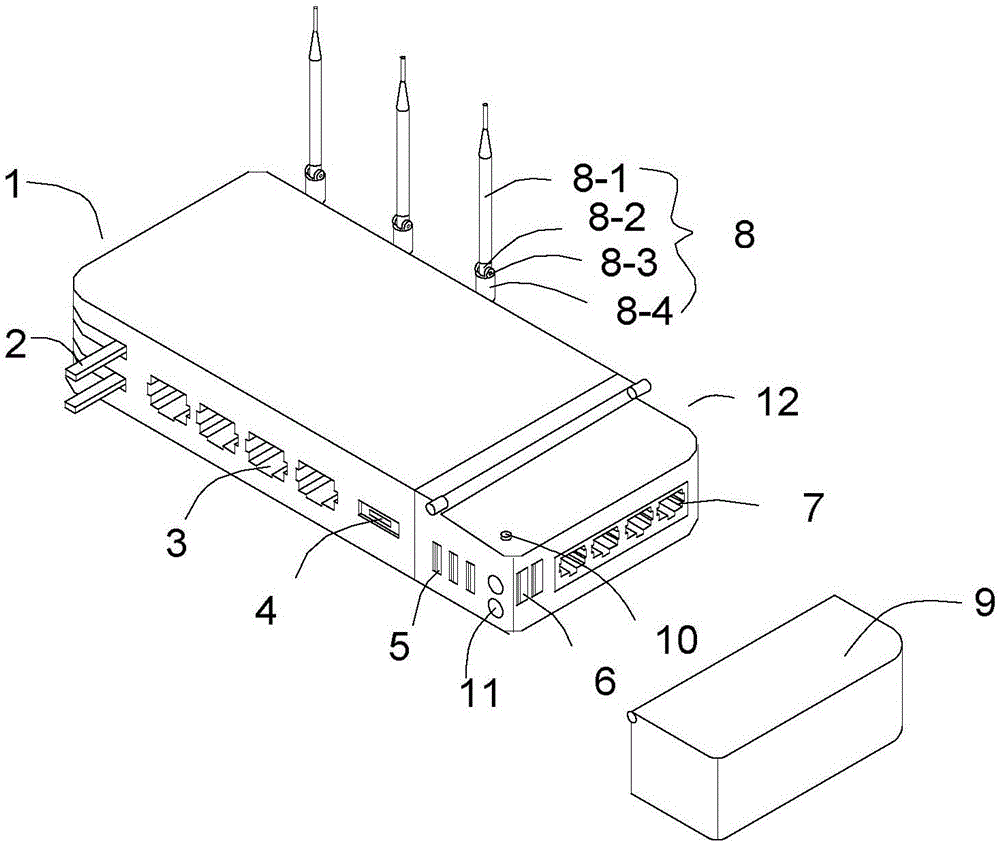
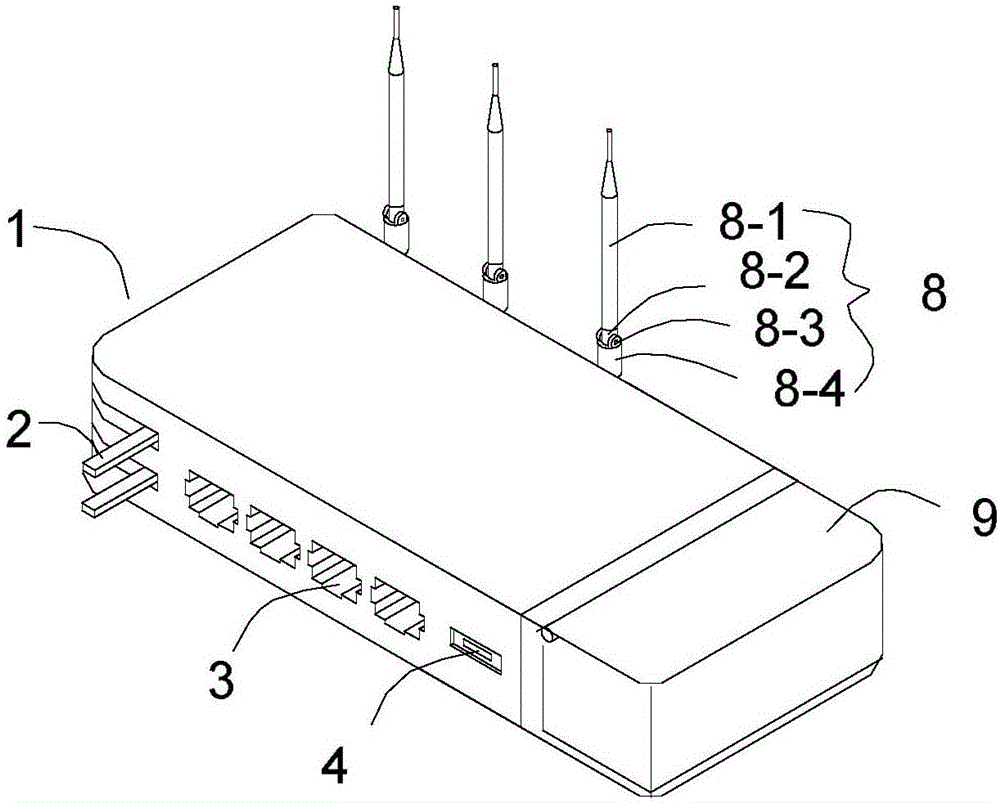
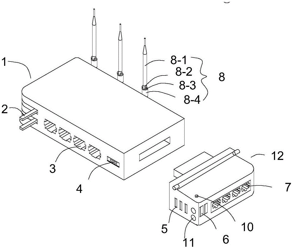
[0021] like Figures 1 to 2 As shown, this embodiment provides a combined multifunctional router, including a router body 1, characterized in that the right end of the router body 1 is detachably connected with an expansion function block 12, and the front side of the router body 1 is provided with a signal The input port 4 and a plurality of signal output ports 3, the router main body 1 is hingedly provided with a charging head 2 that can be hidden in the router main body 1, and the rear side of the router main body 1 is hingedly provided with three identical antenna mechanisms 8, said A plurality of additional signal output ports 7 and two LED lighting lamps 11 are arranged on the right side of the expansion function block 12, and the expansion function block 12 is connected with a dustproof cover 9 through a hinge mechanism.

[0022] The router main body 1 and the expansion function block 12 are connected through snap-in.

[0023] This embodiment is improved on the basis o...

Embodiment 2

[0025] This embodiment has been further optimized on the basis of Embodiment 1, specifically as follows:

[0026] The inside of the expansion function block 12 is provided with a power storage unit, and the expansion function block 12 is provided with a USB interface A5 and a USB interface B6 with different output powers, and both the USB interface A5 and the USB interface B6 are electrically connected to the power storage unit, and the USB interface The output current of A5 is 1A, and the output current of USB interface B6 is 2A.

[0027] The said extended function block 12 is provided with an LED light switch 10 .

[0028] The antenna mechanism 8 includes an antenna lead-out tube 8-4 hinged on the router main body 1, and an angle adjustment shaft 8-3 is provided in a rotating sleeve at the outlet of the antenna lead-out tube 8-4, and the angle adjustment shaft 8-3 is connected to the antenna hinge shaft 8-2. One end is hinged, and the other end of the antenna hinge shaft 8-...


PUM


Abstract

The invention discloses a combined type multifunctional router, which relates to the technical field of routers. The router comprises a router main body. The right end of the router main body is detachably connected with an expanded function block. The front side of the router main body is provided with a signal input port and multiple signal output ports. The router main body is articulated with a charging head which can be hidden inside the router main body. The back side of the router main body is articulated with three identical antenna mechanisms. The right side of the expanded function block is provided with a plurality of additional signal output ports and two LED illumination lights. The expanded function block is connected with a dust cover by a hinge mechanism. According to the invention, the structure of the router is simple; the output ports can be expanded to serve as chargers and illumination lights.

Description

technical field [0001] The present invention relates to the technical field of routers, in particular to a combined multifunctional router. Background technique [0002] As a hub device connecting various LANs and WANs in the Internet, routers have been widely used in various industries. [0003] The function of the antenna is to transmit and receive electromagnetic wave signals. The antennas equipped with existing wireless routers generally can only rotate in a fixed plane around the installation axis, and do not have other plane angle adjustment functions. Therefore, in order to ensure that the antenna can be in various situations Optimum angle to meet the wireless router Internet access speed and coverage standards, people sometimes have to often move the wireless router body to adjust the angle of the antenna in other planes. And moving the router body often involves the corresponding adjustment of the network cable, which is very inconvenient, and most of the existing ...

Claims


Application Information

Patent Timeline
Patent Type & Authority Applications(China)
IPC IPC(8): H04L12/771H04L45/60
CPCH04L45/60
Inventor 程飞
Owner 成都捷科菲友信息技术有限公司
Learn More