A permanent magnet positioning tool for surface-mounted permanent magnet motor

A permanent magnet motor, positioning tooling technology, applied in the direction of electromechanical devices, manufacturing motor generators, electrical components, etc., can solve the problems of complex processing technology, inaccurate installation, large electromagnetic force, etc., to simplify the processing technology and ensure positioning accuracy. , the effect of improving production efficiency

Active Publication Date: 2018-05-29
中国船舶重工集团公司第七一二研究所
View PDF5 Cites 0 Cited by
  • Summary
  • Abstract
  • Description
  • Claims
  • Application Information

AI Technical Summary

Problems solved by technology

Due to the relatively large magnetic field, the installation and fixation of surface-mounted magnets is more troublesome. First, the electromagnetic force is large, and second, the positioning accuracy of the magnets is not easy to guarantee.
[0004] At present, for the installation of surface-mounted permanent magnets, one is to use simple tooling for positioning and installation, but this simple tooling is likely to lead to inaccurate installation, and the cumulative error is relatively large, which may eventually affect the performance of the motor; the second is to paste the magnetic steel The positioning groove of the magnetic steel is processed on the outer surface of the motor. Although this method solves the problem of installation accuracy, the processing technology is complicated, which greatly increases the processing cost of the motor and reduces the efficiency.

Method used


Image

  • A permanent magnet positioning tool for surface-mounted permanent magnet motor
  • A permanent magnet positioning tool for surface-mounted permanent magnet motor
  • A permanent magnet positioning tool for surface-mounted permanent magnet motor

Examples


Embodiment 1

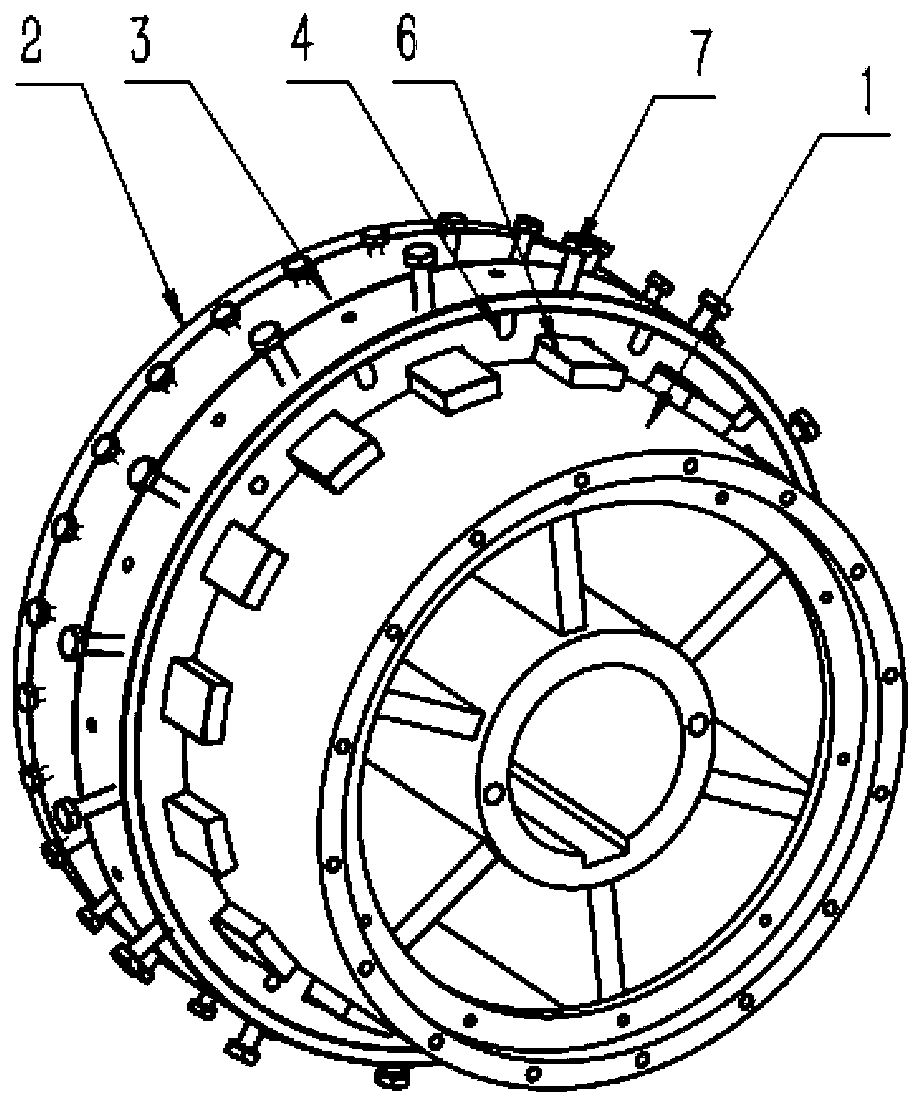
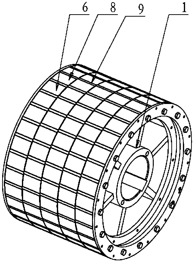
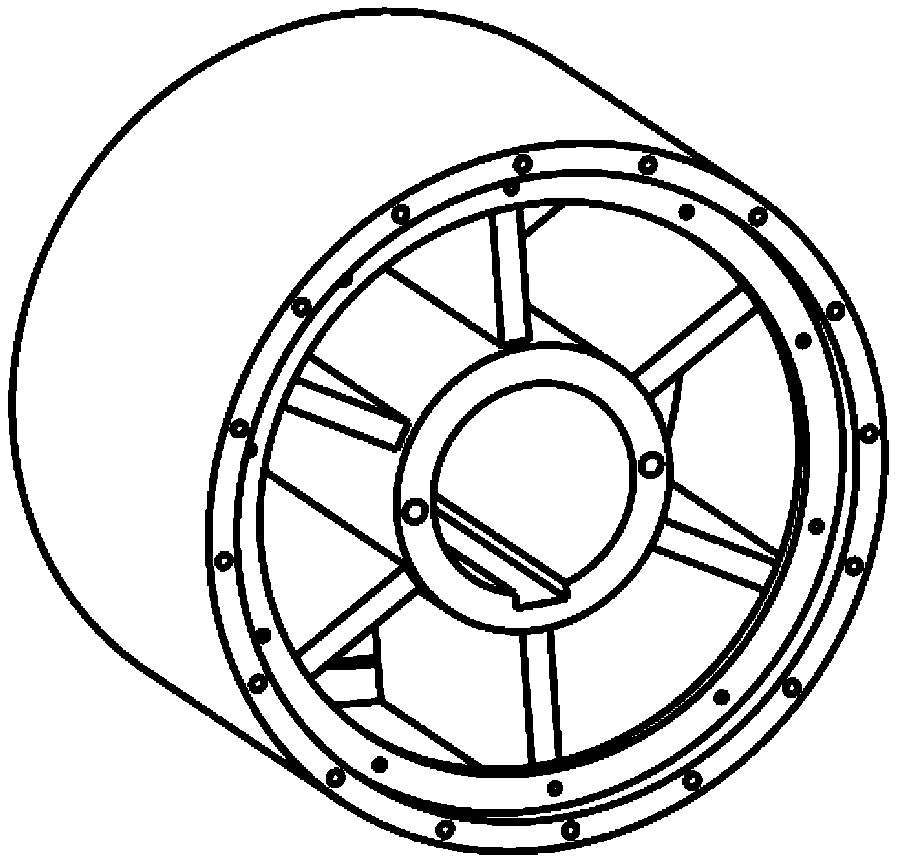
[0026] refer to figure 1 Shown is the general drawing of the permanent magnet installation tooling, which includes a cylindrical skeleton 1 with openings at both ends. The skeleton 1 is an ordinary carbon steel skeleton, a silicon steel skeleton or other magnetic material skeletons. The inside of the skeleton 1 A plurality of reinforcing ribs are also arranged according to the law, and coaxial axial positioning plates 2, radial positioning rings 3 and tangential positioning rings 4 are successively arranged on the outer circumference of the skeleton 1, and the axial positioning plates 2 and the skeleton 1 is provided with a first positioning member, wherein the first positioning member is a bolt, a pin or a spring pressure rod, and the axial positioning plate 2 is provided with a first outer stop 21, a first inner stop 22 and a second A positioning hole 23, the radial positioning ring 3 is provided with a second positioning hole 31, a second inner stop 34 and a second outer st...

Embodiment 2

[0039] The difference from Example 1 is that the frame 1 is not made of steel plates, but laminated with silicon steel sheets.

Embodiment 3

[0041] The difference from Example 1 is that the permanent magnets are not segmented in the axial direction, and limited by the processing technology, the length of the common permanent magnets at present is difficult to exceed 60 mm. If the permanent magnets with a length of more than 60 mm are required, the axial segment is mostly used. If the length is less than 60mm, the axial non-segmented method is adopted.


PUM


Abstract

The invention discloses a permanent magnet positioning tool of a surface-mounted permanent magnet motor. The permanent magnet positioning tool comprises a skeleton, an axial positioning plate, a radial positioning ring and a tangential positioning ring, wherein a first positioning piece is arranged between the axial positioning plate and the skeleton; a first male end, a first female end and a first positioning hole are formed in the axial positioning plate; a second positioning hole, a second female end and a second male end matched with the first male end are formed in the radial positioning ring; a plurality of threaded holes are formed in the radial positioning ring; a plurality of notches and U-shaped positioning holes are formed in the tangential positioning ring; the outer circumference of the tangential positioning ring is matched with the second female end; the first female end is matched with the inner circumference of the tangential positioning ring and the outer circumference of the skeleton; and each of the positioning hole, the second positioning hole and the U-shaped positioning holes is internally provided with a second positioning piece. The permanent magnet positioning tool has the characteristics of accurate positioning, convenient operation, high mounting efficiency, capability of being repeatedly used and the like, and is particularly suitable for being used in production and manufacturing of permanent magnet motors with high-performance and batched surface-mounted magnets.

Description

technical field [0001] The invention belongs to the technical field of permanent magnet motor manufacturing, in particular to a permanent magnet positioning tool for surface-mounted permanent magnet motors, and is particularly suitable for surface-mounted permanent magnet motors produced in batches and on a large scale. Background technique [0002] With the improvement of the performance of permanent magnet materials and the decline of prices, permanent magnet motors have gradually entered the field of industrial and civilian motors. Compared with traditional electric excitation motors, permanent magnet motors have the advantages of compact structure, small size, light weight, simple and reliable structure, and high efficiency. The varieties and application fields of permanent magnet motors continue to expand. [0003] According to the different placement methods of permanent magnets, permanent magnet motors can be divided into surface mount type and built-in type. Compare...

Claims


Application Information

Patent Timeline
Patent Type & Authority Patents(China)
IPC IPC(8): H02K15/03
CPCH02K15/03
Inventor 谢峰杨高贾海媛徐磊陈云华
Owner 中国船舶重工集团公司第七一二研究所
Why Eureka
Try Eureka