A connection node between truss body and concrete structure, truss and method
A concrete structure and connecting node technology, which is applied in the direction of building structure and construction, can solve the problems of difficult construction, long construction period, and difficult to meet the needs of installation and positioning, and meet the requirements of difficult construction, long construction process, and positioning accuracy No. effect
- Summary
- Abstract
- Description
- Claims
- Application Information
AI Technical Summary
Problems solved by technology
Method used
Image
Examples
Embodiment 1
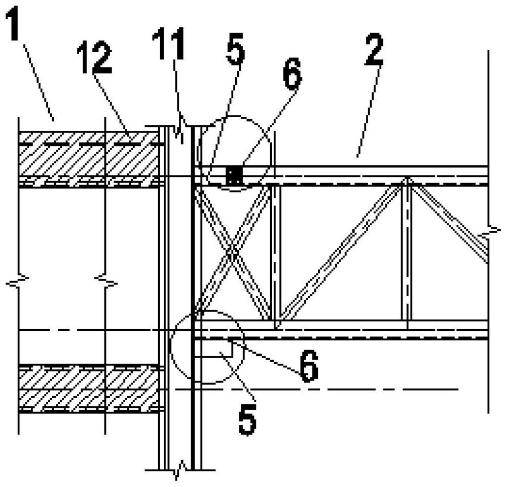
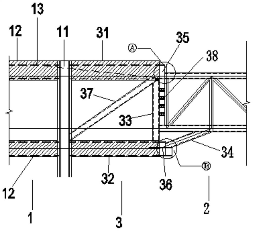
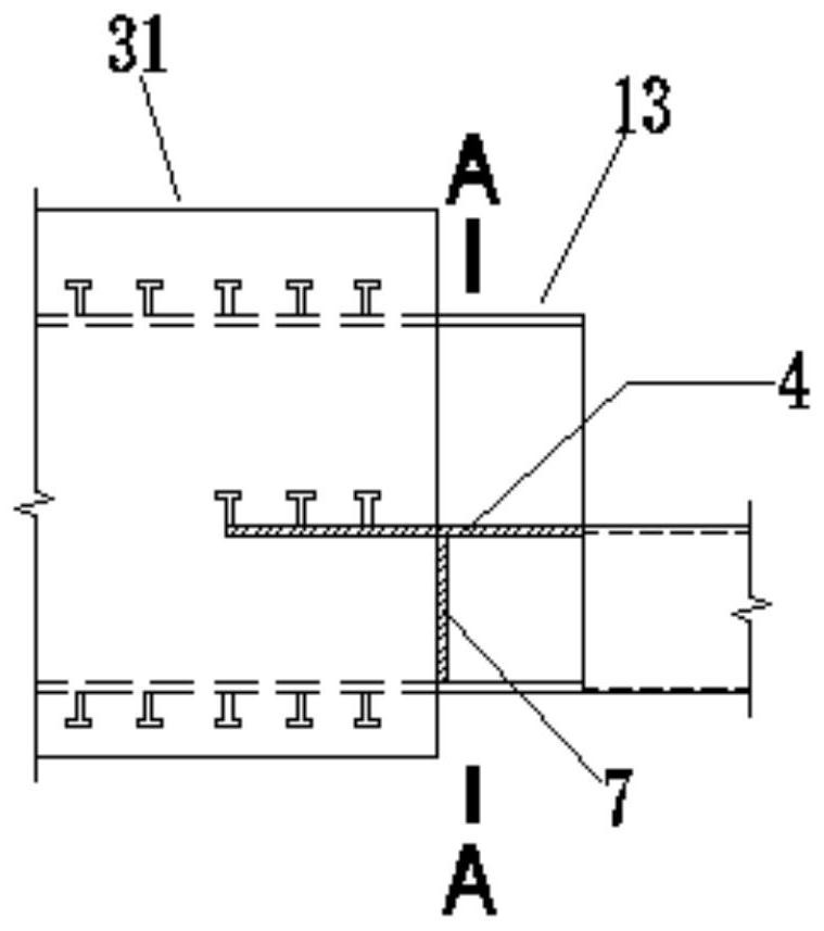
[0045] The invention provides a connection node between the truss body and the concrete structure, such as Figure 2-5 As shown, the concrete structure 1 includes a column 11 and two beams 12 located on one side of the column 11. I-shaped steel 13 is pre-embedded in the two beams 12, and the truss body 2 is a steel truss body, that is to say, the truss body 12 is formed by connecting section steels, specifically, the section steels include one or more of I-shaped steels, T-shaped steels, and H-shaped steels.
[0046] The connection node 3 includes a first cross beam 31 , a second cross beam 32 , a first shaped steel 33 and a second shaped steel 34 .
[0047] The first beam 31 and the second beam 32 are respectively extended from the two beams 12 in the concrete structure 1 .
[0048] It should be noted that the first crossbeam 31 and the second crossbeam 32 are integrally formed with the crossbeam 12 respectively, that is, the shaped steel in the first crossbeam 31 and the se...
Embodiment 2
[0070] The invention also discloses a truss, which includes a truss body and a connection node 3 between the truss body 2 and the concrete structure in Embodiment 1.
[0071] The truss body 2 is an arc structure, such as Figure 6-8 shown.
[0072] The truss body 2 includes an upper chord 21 , a lower chord 22 and at least two webs 23 , the upper chord 21 and the lower chord 22 are arc-shaped, and the upper chord 21 and the lower chord 22 are parallel. The upper chord 21 is used for bearing pressure, and the lower chord 22 is used for bearing tension.
[0073] The web 23 is welded between the upper chord 21 and the lower chord 22 . The web 23 mainly plays a supporting role, thereby reducing the width of the upper chord 21 and the lower chord 22 to ensure the rigidity of the overall structure.
[0074] Upper chord 21, lower chord 22 and web 23 are section steel.
[0075] The number of upper chords 21 is two, and the webs 23 are welded between the two upper chords 21 .
[0...
Embodiment 3
[0078] A method for connecting a truss body to a concrete structure, using the connection node between the truss body and the concrete structure in Embodiment 1, the method comprising the following steps:
[0079] Step 1: Pass the two beams 12 of the concrete structure 1 through the column 11, extend and pour to one end of the truss body 2, and no concrete is poured at the extended end, exposing the I-shaped steel;
[0080] Step 2: welding the two ends of the vertically placed first section steel 33 to the I-shaped steel at the two extension ends respectively;
[0081] Step 3: The I-shaped steel at the first end 35 is welded to the top of the truss body 2;
[0082] Step 4: The I-shaped steel plate at the second end 36 is repaired and welded with a steel plate to form an L-shaped groove. One end of the second steel 34 is welded to the L-shaped groove, and the other end is welded to the bottom of the truss body 2 .
[0083] Using the above connection method, the installation is...
PUM
 Abstract
Description
Claims
Application Information
 - R&D
- Intellectual Property
- Life Sciences
- Materials
- Tech Scout
- Unparalleled Data Quality
- Higher Quality Content
- 60% Fewer Hallucinations
Browse by: Latest US Patents, China's latest patents, Technical Efficacy Thesaurus, Application Domain, Technology Topic, Popular Technical Reports.
© 2025 PatSnap. All rights reserved.Legal|Privacy policy|Modern Slavery Act Transparency Statement|Sitemap|About US| Contact US: help@patsnap.com


