Hydraulic valve element milling clamping fixture

A technology for clamping tooling and hydraulic valve, which is applied in the field of tooling and hydraulic valve core milling and clamping tooling, which can solve the problems of high labor intensity, low processing efficiency, and adverse effects on positioning accuracy.

Pending Publication Date: 2016-07-13
ZHENJIANG HYDRAULICS
View PDF8 Cites 0 Cited by
  • Summary
  • Abstract
  • Description
  • Claims
  • Application Information

AI Technical Summary

Problems solved by technology

[0002] According to the applicant's understanding, fixture is a kind of component commonly used in machinery manufacturing. For a long time, when milling the valve core in the hydraulic steering gear, it has been manually clamped by ordinary flat pliers, which is not only labor-intensive, but also And the processing efficiency is not high
[0003] In particular, the flat-nose pliers rely on the manual screw mechanism to screw in and clamp, and the helix angle of the screw mechanism and the way of applying torque by manual operation also have an adverse effect on the positioning accuracy of the valve core when clamping.

Method used


Image

  • Hydraulic valve element milling clamping fixture
  • Hydraulic valve element milling clamping fixture

Examples


Embodiment 1

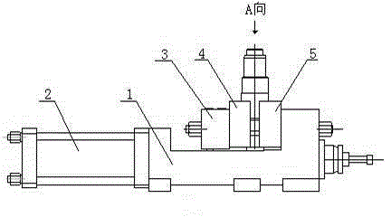
[0015] The hydraulic spool milling and clamping tool of this embodiment is as follows: figure 1 As shown, the base 1 for placing on the milling machine is in a concave shape, and one end is equipped with a hydraulic cylinder 2 installed horizontally, and the piston rod protruding from the hydraulic cylinder 2 is fixedly connected with the push block 3 . The bottom of the pushing block 3 is installed in the chute in the middle of the base 1 to form a horizontal movement pair, and is fixedly connected with the dynamic clamping block 4 by means of fasteners. The opposite side of the dynamic clamping block 4 is equipped with a static clamping block 5 fixed on the other end of the base 1 .

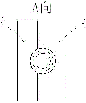
[0016] Such as figure 2 As shown, the middle parts of the opposite end surfaces of the dynamic clamping block 4 and the static clamping block 5 respectively have workpiece positioning circular arc concaves matching the outer circle of the valve core G. The positioning arc concave of the stat...


PUM


Abstract

The invention relates to a hydraulic valve element milling clamping fixture, and belong to the technical field of machining. The fixture comprises a base. One end of the base is provided with a horizontal hydraulic cylinder. A piston rod extended from the hydraulic cylinder is fixedly connected with a pushing block. The pushing block and the base form a horizontal sliding pair, and the pushing block is fixedly connected with a moveable clamping block. The opposite side of the moveable clamping block is provided with a static clamping block fixed on the other end of the base. The middle parts of the opposite end faces of the moveable clamping block and the static clamping block are respectively provided with a workpiece positioning arc groove matched with the outer circle of a valve element. In processing, by pushing of the hydraulic cylinder on the pushing block, the moveable clamping block moves relative to the static clamping block, and by using the positioning arc grooves, an objective of accurately clamping a workpiece is achieved. Since movement of the hydraulic cylinder is not influenced by human factors, and translation generated by the hydraulic cylinder completely does not have additional torsion, clamping is convenient, labor saving, and efficient, and positioning precision after clamping is high.

Description

technical field [0001] The invention relates to a tool, in particular to a hydraulic valve core milling and clamping tool, which belongs to the technical field of mechanical processing. Background technique [0002] According to the applicant's understanding, fixture is a kind of component commonly used in machinery manufacturing. For a long time, when milling the valve core in the hydraulic steering gear, it has been manually clamped by ordinary flat pliers, which is not only labor-intensive, but also And the processing efficiency is not high. [0003] In particular, the flat-nose pliers are screwed in and clamped by a manual screw mechanism, and the helix angle of the screw mechanism and the way of applying torque by manual operation also have an adverse effect on the positioning accuracy when the valve core is clamped. Contents of the invention [0004] The object of the present invention is to provide a hydraulic valve core milling and clamping tool that is easy to op...

Claims


Application Information

Patent Timeline
Patent Type & Authority Applications(China)
IPC IPC(8): B23Q3/08
Inventor 焦文瑞秦志文潘骏张燕沈启志宣曙江阮永强
Owner ZHENJIANG HYDRAULICS
Why Eureka
Try Eureka