
Power spring-based voltage sag treatment circuit and treatment method thereof

A technology of electric spring and voltage sag, applied in the direction of AC network voltage adjustment, reactive power compensation, etc., to achieve the effects of improving voltage sag tolerance, voltage sag improvement, and strong practicability

Inactive Publication Date: 2017-01-04
STATE GRID JIANGSU ELECTRIC POWER CO ELECTRIC POWER RES INST +2
View PDF4 Cites 10 Cited by
  • Summary
  • Abstract
  • Description
  • Claims
  • Application Information

AI Technical Summary

Problems solved by technology

The shortcoming is that although they can effectively suppress the voltage sag, they are all based on the existing mode, that is, first determine the demand for compensation voltage (energy) required by the sag-sensitive equipment, and then provide the corresponding power generation

Method used


Image

  • Power spring-based voltage sag treatment circuit and treatment method thereof
  • Power spring-based voltage sag treatment circuit and treatment method thereof
  • Power spring-based voltage sag treatment circuit and treatment method thereof

Examples


Embodiment Construction

[0030] The present invention will be further described below in conjunction with the accompanying drawings. The following examples are only used to illustrate the technical solution of the present invention more clearly, but not to limit the protection scope of the present invention.

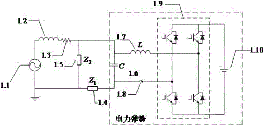
[0031] Such as figure 1 As shown, the electric spring-based voltage sag control circuit provided by the present invention includes electric springs and sag-sensitive loads connected in parallel at both ends of the single-phase grid. After the electric springs are connected in series with non-sag-sensitive loads, they are Drain-sensitive loads are connected in parallel. When a voltage sag occurs, the electric spring instantaneously acts to provide reactive power support for the sag-sensitive load to raise the voltage to within the normal operating range, and transfers the voltage fluctuation to the non-sag-sensitive load to ensure the sag Voltage stabilization for type sensitive loads.

[0032...


PUM


Abstract

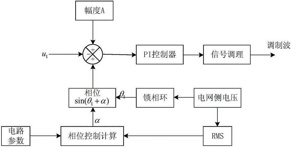
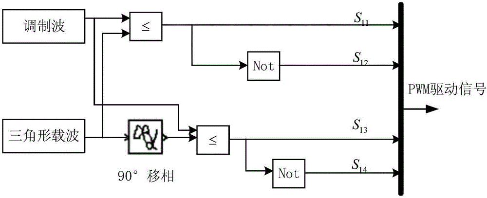
The present invention discloses a power spring-based voltage sag treatment circuit, comprising a power spring and a sag sensitive load that is connected to both ends of a one-phase electrical network in parallel. The power spring is connected to a non-sag sensitive load in series, and then is connected to the sag sensitive load in parallel. The present invention further discloses a power spring-based voltage sag treatment method, comprising collecting a sag voltage feedback signal u1 on both ends of a sag sensitive load by using a PT; comparing the u1 with a given reference sinusoidal quantity u1_ref to a PR controller, performing subtraction between the both and then sending a difference to the PR controller for PR regulation, and using the difference as a CPS-SPWM modulating wave after signal conditioning; comparing the modulating wave with an isosceles triangle carrier, and using the modulating wave as a drive signal of a single-phase voltage source type inverter. The power spring runs in a distributed manner, and can be used on a particular sag sensitive load by using different connection manners according to actual needs without affecting stable operation of an electrical network, and has strong practicality.

Description

technical field [0001] The invention relates to a voltage sag control circuit based on an electric spring, and also relates to a voltage sag control method based on an electric spring, which belongs to the technical field of electric power systems. Background technique [0002] Voltage sag, also known as voltage sag, voltage sag or voltage sag, voltage sag is an event in which the root mean square value of the power supply voltage suddenly drops in a short period of time and then quickly returns to a normal state. The typical time is generally 0.5 to 30 cycles time. The Institute of Electrical and Electronics Engineers (IEEE) defines voltage sag as: the effective value of the power frequency voltage at a certain point in the power supply system suddenly drops to 90% to 10% of the rated voltage, and then recovers after a short duration of 10ms to 1min normal. The International Electrotechnical Commission (IEC) defines that the effective value of the power frequency voltage ...

Claims


Application Information

Patent Timeline
Patent Type & Authority Applications(China)
IPC IPC(8): H02J3/12H02J3/16
CPCH02J3/12H02J3/16Y02E40/30
Inventor 陈兵黄强顾伟罗珊珊储佳伟王旭冲邱海峰费骏韬
Owner STATE GRID JIANGSU ELECTRIC POWER CO ELECTRIC POWER RES INST
Learn More