System wave aberration detection method capable of calibrating system errors

A detection method and system error technology, applied in the field of optical detection, can solve problems such as difficulty in implementation, and achieve the effects of improving measurement accuracy, being easy to implement, and improving measurement accuracy

Inactive Publication Date: 2017-01-04
CHANGCHUN INST OF OPTICS FINE MECHANICS & PHYSICS CHINESE ACAD OF SCI
View PDF7 Cites 11 Cited by
  • Summary
  • Abstract
  • Description
  • Claims
  • Application Information

AI Technical Summary

Problems solved by technology

However, this method has strict requirements on the technical indicators such as eccentricity and tilt during the rotation process of the projection objective lens under test. Therefore, not only a rotating mechanism with strong load-bearing capacity is required, but the rotating mechanism also requires extremely high positioning accuracy and repeatability. , which is very difficult to realize in engineering
And the method of separating systematic errors by rotating the projection objective under test has significant limitations for high NA projection objectives using mirrors and off-axis optics

Method used


Image

  • System wave aberration detection method capable of calibrating system errors
  • System wave aberration detection method capable of calibrating system errors
  • System wave aberration detection method capable of calibrating system errors

Examples


Embodiment Construction

[0038] In order to solve the problem that the existing interferometry method causes systematic errors in the measurement results and affects the detection accuracy, the present invention proposes a systematic wave aberration detection method capable of calibrating the systematic errors.

[0039] In order to make the object, technical solution and advantages of the present invention clearer, the present invention will be described in further detail below in conjunction with specific embodiments and with reference to the accompanying drawings.

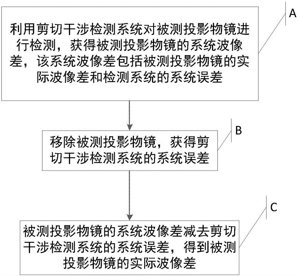
[0040] see figure 1 , figure 1 A flow chart of a method for detecting systematic wave aberration capable of calibrating systematic errors according to an embodiment of the present invention is shown. The system wave aberration detection method includes:

[0041] Step A: Using the shearing interference detection system to detect the projected projection objective lens to obtain the systematic wave aberration of the projected projection ...


PUM


Abstract

The invention provides a system wave aberration detection method capable of calibrating system errors. The system wave aberration of a projection objective to be detected is subtracted from the system errors of a shear interference detection system to obtain the actual wave aberration of the projection objective to be detected, the influence of the system errors is eliminated, and measuring accuracy is improved. A filtering function can be achieved by a small hole space filter, aberration caused by a lighting system and a first convergence lens can be eliminated, and detection accuracy of the system wave aberration is improved. Only +/- level diffraction light can pass a window in the space filter, zero and higher level diffraction light is intercepted by the space filter, so that noise is reduced, and measuring precision is improved.

Description

technical field [0001] The invention relates to the technical field of optical detection, in particular to a system wave aberration detection method capable of calibrating system errors. Background technique [0002] Optical projection lithography is an optical exposure process that uses the principle of optical projection imaging to transfer the high-resolution IC pattern on the mask to the rubber-coated silicon wafer by exposure. It is the most widely used in the manufacturing process of VLSI The lithography technology with the widest and fastest technological progress. The lithography process directly determines the feature size of large-scale integrated circuits and is a key process in the manufacture of large-scale integrated circuits. The projection objective lens of a lithography machine is the core component of the lithography process and the most difficult subsystem. [0003] After years of development, the exposure wavelength of the lithography machine has develop...

Claims


Application Information

Patent Timeline
Patent Type & Authority Applications(China)
IPC IPC(8): G03F7/20G01M11/02
CPCG01M11/0242G03F7/706
Inventor 于长淞高松涛彭石军苗二龙隋永新杨怀江
Owner CHANGCHUN INST OF OPTICS FINE MECHANICS & PHYSICS CHINESE ACAD OF SCI
Why Eureka
Try Eureka