Laser beam coupling detection and debugging structure and detection and debugging method

A debugging method and a laser beam technology, applied in the application field of laser technology, can solve the problem that the coupling efficiency needs to be improved, and achieve the effects of avoiding loss, high coupling efficiency, and improving the qualification rate

Active Publication Date: 2018-08-10
SHANGHAI RAYKEEN LASER TECH CO LTD
View PDF7 Cites 0 Cited by
  • Summary
  • Abstract
  • Description
  • Claims
  • Application Information

AI Technical Summary

Problems solved by technology

[0007] However, the coupling efficiency of the laser beam coupled to the optical fiber in the prior art still needs to be improved

Method used


Image

  • Laser beam coupling detection and debugging structure and detection and debugging method
  • Laser beam coupling detection and debugging structure and detection and debugging method
  • Laser beam coupling detection and debugging structure and detection and debugging method

Examples


Embodiment Construction

[0037] It can be seen from the background art that the coupling efficiency of the laser beam coupled to the optical fiber in the prior art still needs to be improved.

[0038] After analysis, it is found that in the coupling technology of laser and optical fiber, the relative positional relationship between laser beam and optical fiber is mainly controlled by mechanical structure. Therefore, in order to obtain high coupling efficiency, in addition to strictly satisfying the coupling conditions, the mechanical structure Accuracy is also critical.

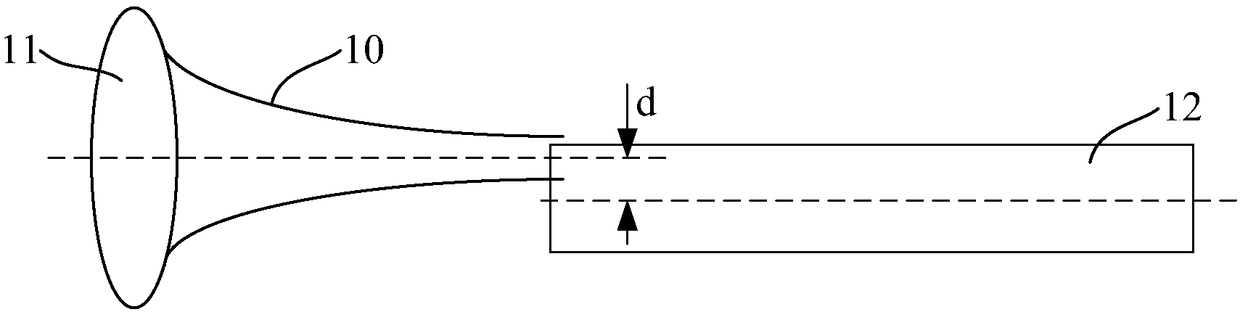
[0039] Due to the limitation of processing accuracy or the mismatch in the assembly process, it is inevitable that there will be azimuth alignment errors, mainly due to the azimuth alignment errors between the coupling mirror and the optical fiber, resulting in a decrease in coupling efficiency. The alignment error includes the lateral displacement error between the coupling mirror and the fiber, combined with the reference figure 1...


PUM


Abstract

The invention provides a laser beam coupling detecting and debugging structure and a detecting and debugging method. The detecting and debugging structure comprises a laser emitter used for emitting lasers, a coupling mirror positioned on a laser optical path emitted by the laser emitter and used for gathering the lasers to form a laser beam, an adjusting rack used for placing the coupling mirror and adjusting the position of the coupling mirror, an optical fiber positioned on a laser beam optical path, and an optical fiber joint at the connection between the coupling mirror and the optical fiber. The coupling mirror is positioned between the optical fiber and the laser emitter. The end surface of the optical fiber is provided with a light spot reception layer, and the light spot reception layer has a central area. The center of the central area is superposed with the center of the end surface of the optical fiber. The invention can determine whether the position of the coupling mirror is qualified or not and adjust the coupling mirror to a quailed position, and thus the coupling efficiency of coupling the laser beam in the optical fiber is raised.

Description

technical field [0001] The invention relates to the application field of laser technology, in particular to a laser beam coupling detection and debugging structure and a detection and debugging method. Background technique [0002] Laser is one of the great inventions of mankind in the 20th century, and it is widely used in many fields. The application of laser in medicine has opened up a new discipline, using new technology of laser to research, diagnose, prevent and treat diseases. Laser has been widely used in internal medicine, surgery, gynecology, pediatrics, eye, ENT, oral cavity, skin, tumor, acupuncture, physical therapy and other clinical departments. It not only opens up a new research path for the study of life sciences and the occurrence and development of diseases, but also provides a new means for clinical diagnosis and treatment of diseases. [0003] Laser transmission through optical fiber can reach diseased tissues in various parts of the human body for va...

Claims


Application Information

Patent Timeline
Patent Type & Authority Patents(China)
IPC IPC(8): G02B6/42
CPCG02B6/4204G02B6/4224G02B6/4226G02B6/4227
Inventor 王援柱罗娇林王昕
Owner SHANGHAI RAYKEEN LASER TECH CO LTD
Why Eureka
Try Eureka