
A full armor mud discharge pipe and its production method

A technology of mud discharge pipe and armor, applied in the field of full armor mud discharge pipe, can solve the problems of loss of fastening function of multi-layer steel fastening layer, technical defects of reliability of use quality, matching of difficult metal composite mud discharge pipe, etc. Achieve the effect of expanding the applicable field and scope of use, reliable pipeline direction adjustment technology, and highlighting substantive characteristics

Active Publication Date: 2018-08-10
姜考成
View PDF3 Cites 0 Cited by
  • Summary
  • Abstract
  • Description
  • Claims
  • Application Information

AI Technical Summary

Problems solved by technology

[0003] Due to the product defects in the existing technology itself, there are the following deficiencies: one is that although the mud discharge rubber pipe has a certain bending performance, because the curvature of the direction of the mud discharge pipeline is adjusted, it depends on the whole body from inside to outside. The deformation scheme is realized. For the self-floating mud discharge rubber pipe, this deformation is completed by the elastic deformation of each part of the pipe body, and the elastic deformation of each part is for the same circumferential section of the pipe body. There are dual stresses of tension and compression, so this technical solution itself has the problem that in the absence of external bending force, the elastic deformation of the self-floating mud discharge rubber pipe itself cannot guarantee to meet the specified bending degree. The defects of the requirements, especially the non-matching defects shown when it is used with the bundled floating metal mud discharge pipe are more prominent; The technical solution of grinding the steel ring is to improve the wear resistance of the rubber pipe. When the mud discharge rubber pipe is in use, the solid material to be transported is repeated in a conveying pipeline composed of an organic adhesive and a wear-resistant steel ring. Running, because the inner wall made of organic adhesive and wear-resistant steel ring will be repeatedly collided by solid materials, the degree of wear of organic adhesive and wear-resistant steel ring is not the same, which will not only affect the conveying speed due to conveying resistance, but also directly It affects the service life. Due to the inconsistent wear resistance of the inner pipe wall, it is difficult to use it with a better metal composite mud discharge pipe, especially in the operation of transporting ore and coral reefs in the South China Sea under harsher operating conditions. The matching phenomenon is more prominent
With the deepening of research and the gradual development of product trial production, the technical defects of this technical scheme have also been revealed, which mainly exist in the following: one is that the single-layer pipe body structure is made of cast steel for the tapered pipe, The hardness reaches about HRC60, good rigidity and poor toughness. Once impact occurs during transportation and use, it is easy to produce cracks or even broken technical defects, and there may be hidden dangers of serious technical defects in terms of quality and reliability in use; the second is the cord The multi-layer steel fastening layer in the strong elastic material layer is in a free state during the vulcanization process, and the steel wire and steel belt gradually free to the non-restricted area, and the originally wound steel wire and steel belt fastening layer loosen, causing The fastening layer cannot play its proper fastening function, especially when a steel wire in the multi-layer steel fastening layer breaks, causing the set multi-layer steel fastening layer to lose its proper fastening function, resulting in The connection and fastening layer coated on the outside of the pipe body is prone to quality accidents of peeling, especially when the armored mud discharge pipe is faced with high pressure, high flow rate, and high wear environment. The existence of this technical defect is a quality accident in use. The occurrence of many uncertain factors

Method used


Image

  • A full armor mud discharge pipe and its production method
  • A full armor mud discharge pipe and its production method
  • A full armor mud discharge pipe and its production method

Examples


Embodiment 1

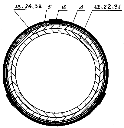
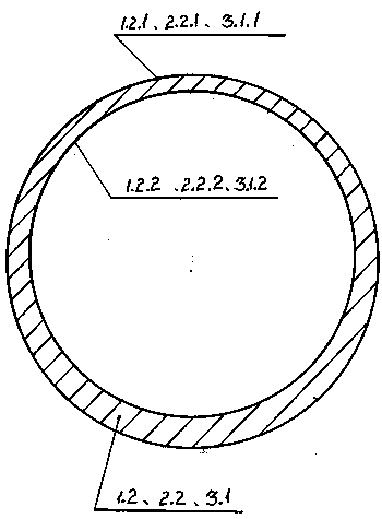
[0037] A kind of full armor mud discharge pipe of embodiment 1 of the present invention (referring to figure 1 , figure 2 ), including a pipe body and a connecting fastening layer, the pipe body is an inlet end pipe 1 with a flange, 5 tapered pipes 2, and an outlet end pipe 3 with a flange in order to be assembled as a whole . The inlet end connecting pipe 1 is a combination of the inner steel pipe 1.2 and the outer layer steel pipe 1.3, an inlet end connecting pipe flange 1.1 is provided at the inlet end, and two inlet end connecting pipes 1 are arranged on the outer side of the outer layer steel pipe 1.3. The annular positioning fastening ring 1.4, the outlet end of the inlet pipe 1 is provided with a tapered boss 1.5 of the inlet pipe 1 inserted into the inner chamber 2.1 of the inlet end of the tapered pipe 2, and the inlet pipe flange 1.1 is connected to the outer Several support plates 1.6 for the inlet end pipes are provided between the outer walls of the steel pipes...

Embodiment 2

[0048] A kind of full armor mud discharge pipe of embodiment 2 of the present invention (referring to image 3 , Figure 4 , Figure 5 ), including a pipe body and a connecting fastening layer, the pipe body is an inlet end pipe 1 with a flange, 8 tapered pipes 2, and an outlet end pipe 3 with a flange, which are armored and assembled in sequence . The inlet end connecting pipe 1 is a combination of the inner steel pipe 1.2 and the outer layer steel pipe 1.3, an inlet end connecting pipe flange 1.1 is provided at the inlet end, and two inlet end connecting pipes 1 are arranged on the outer side of the outer layer steel pipe 1.3. The annular positioning fastening ring 1.4, the outlet end of the inlet pipe 1 is provided with a tapered boss 1.5 of the inlet pipe 1 inserted into the inner chamber 2.1 of the inlet end of the tapered pipe 2, and the inlet pipe flange 1.1 is connected to the outer Several support plates 1.6 for the inlet end pipes are provided between the outer wa...

Embodiment 3

[0059] A kind of full armor mud discharge pipe of embodiment 3 of the present invention (referring to image 3 , Figure 4 , Figure 5 , Figure 6 ), including the pipe body and the connecting fastening layer compounded on the outside of the pipe body, the pipe body is an inlet end pipe 1 with a flange, 10 tapered pipes 2, and an outlet end with a flange The connecting pipe 3 is assembled into one piece of armor sequentially. The inlet connecting pipe 1 and the outlet connecting pipe 3 are composed of inner steel pipes 1.2, 3.1 and outer steel pipes 1.3, 3.2. The inner steel pipes 1.2 and 3.1 are wear-resistant layers. The wear-resistant high-chromium cast iron pipe is prepared by grinding the steel plate through the process of batching, blanking, pressing and welding. The outer steel pipe 1.3 and 3.2 are the reinforcement layer, and the ordinary spiral low-carbon steel pipe coil is used. The inlet end connection pipe 1 is composed of an inner steel pipe 1.2 and an outer laye...


PUM


Abstract

The invention discloses a full-armor sludge discharging pipe and a production method thereof and belongs to the technical field of dredging engineering equipment. The invention adopts the technical scheme that the full-armor sludge discharging pipe is provided with at least two groups of cord fabric strong elastic material layers, each group of cord fabric strong elastic material layer is formed by obliquely winding a plurality of layers of double-sided adhesive chemical fiber cord fabrics and a pipe body and oppositely coating the plurality of layers into a whole, a plurality of multilayer rigid fastening layers are arranged at the part where the outer side of each group of cord fabric strong elastic material layer is corresponding to an annular positioning and fastening ring for the pipe body, the two end parts of each group of each of cord fabric strong elastic material layer are outer flanges, and the two groups of cord fabric strong elastic material layers and the plurality of multilayer rigid fastening layers are sequentially arranged in a circulating manner. Compared with the prior art, the full-armor sludge discharging pipe and the production method thereof disclosed by the invention have the benefits that the technical scheme is reliable, and not only is the bending requirement of adjusting the direction of the sludge discharging pipe met, but also the outstanding substantive characteristic of comprehensively improving the use performance of the metallic sludge discharging pipe and the significant progress are achieved.

Description

technical field [0001] The invention relates to the technical field of related equipment used in dredging engineering, in particular to the technical field of a full-armor mud discharge pipe and a production method thereof. Background technique [0002] The construction of mechanical dredging projects such as river courses, waterways, harbor basin dredging, harbor shoals, and wharf foundation trenches all require a large number of mud discharge pipelines connected by mud discharge pipes to achieve transportation, and the indispensable in the entire mud discharge pipeline The mud discharge elbow used to adjust the direction of the mud discharge pipeline, most of the self-floating mud discharge rubber pipes that have been used so far, because the self-floating mud discharge rubber pipe is used to transport solid materials with sharp edges such as rocks, coral reefs, ores, etc. It will soon be worn out and lose its use value, which will cause the entire dredging engineering sys...

Claims


Application Information

Patent Timeline
Patent Type & Authority Patents(China)
IPC IPC(8): F16L11/00F16L33/02F16L23/032F16L23/024
CPCF16L11/00F16L23/024F16L23/032F16L33/02
Inventor 姜考成唐永胜陈宏礼姜作亮
Owner 姜考成
Learn More