
Hydrogen sulfide automatic treatment device for oil and gas wells

An automatic treatment, hydrogen sulfide technology, applied in wellbore/well components, production fluids, earth-moving drilling and other directions, can solve the problems of accelerated pipeline corrosion rate, large equipment investment, and difficult operation, etc., to solve the problem of hydrogen sulfide corrosion, The effect of low power consumption and low operating cost

Active Publication Date: 2019-04-09
CHINA PETROLEUM & CHEM CORP +1
View PDF7 Cites 0 Cited by
  • Summary
  • Abstract
  • Description
  • Claims
  • Application Information

AI Technical Summary

Problems solved by technology

Wet process mainly includes absorption method and wet oxidation method, etc. At present, the desulfurization process used in the petroleum industry generally has problems such as complex process, large floor area, difficult operation, large equipment investment and high operating cost, which obviously cannot meet the requirements. Practical requirements for oil and gas field production
[0003] At present, the most used method is to inject a desulfurizer into the pipeline. The desulfurizer is an alkaline solution of hydrogen sulfide in the reducing liquid phase. It is continuously injected into the pipeline according to a certain amount through the chemical pump to neutralize the hydrogen sulfide and generate The effect of neutral salt, but the price of desulfurization agent is relatively high, and it is not easy to store. For the agent accidentally leaked during operation, in addition to certain damage to the human body, it will also cause pollution to the soil
And if the ratio is not proper, the corrosion rate of the pipeline will be accelerated

Method used


Image

  • Hydrogen sulfide automatic treatment device for oil and gas wells

Examples


Embodiment Construction

[0016] In order to make the above and other objects, features and advantages of the present invention more comprehensible, the preferred embodiments are listed below and shown in the accompanying drawings in detail as follows.

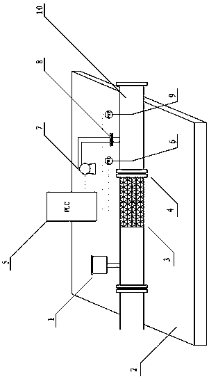
[0017] The invention provides a field treatment device for hydrogen sulfide removal of oil and gas well output, such as figure 1 As shown, it includes the base 2 of the dehydrogen sulfide mine processing device, and also includes a static mixer 3 arranged on the base 2, and an oxidant inlet 1 arranged on the static mixer 3, and an oxidizer inlet 1 1. The bottom is connected to the static mixer 3 by welding; the hydrogen sulfide removal field treatment device also includes a reduction pipeline 10 arranged on the base 2 and connected to the static mixer 3 by flange or welding, and the static mixing Both the device 3 and the reduction pipeline 10 are placed on the base 2 through pipeline support piers; the reduction pipeline 10 includes a first pH sensor ...


PUM


Abstract

The invention discloses an automatic oil / gas well hydrogen sulfide treatment device which comprises a static mixer, an oxidant inlet, a reduction pipeline, a pH sensor, a reducing agent inlet, a metering pump and a control cabinet, wherein an oxidant is fed into the static mixer from the oxidant inlet and is mixed with an oil / gas well product in the static mixer; fluid obtained after mixing flows into the reduction pipeline from the static mixer; the reducing agent fed from the reducing agent inlet is pumped into the reduction pipeline from the metering pump; the pH sensor is used for transmitting a detected pH value of the fluid in the reduction pipeline to the control cabinet; the control cabinet is used for controlling the rotation speed of the metering pump according to the pH value of the fluid, and used for adjusting the addition amount of the reducing agent. The automatic oil / gas well hydrogen sulfide treatment device has the characteristics of being small in investment, small in size, convenient to mount, low in operation cost, good in automatic control and the like, and the long-term problem that operators can be hurt by leakage as a pipeline is corroded by hydrogen sulfide in the oil exploitation industry can be solved.

Description

technical field [0001] The invention relates to the technical field of oilfield exploitation, in particular to an automatic hydrogen sulfide treatment device for oil and gas wells used for oil and gas well output. Background technique [0002] Hydrogen sulfide is highly toxic, highly corrosive and odorous, and is also the main sulfur-containing component in oil and gas. With the increase of energy demand, the exploration and development of high hydrogen sulfide oil and gas fields in my country has been continuously intensified. Hydrogen sulfide in the output of oil and gas wells not only causes corrosion of pipelines and equipment, but also seriously threatens personal safety. There are many processes for removing hydrogen sulfide in the process of oil and gas field development. However, simple, economical and effective hydrogen sulfide removal technology and equipment are still difficult problems that need to be continuously explored and studied. Oilfield production has t...

Claims


Application Information

Patent Timeline
Patent Type & Authority Patents(China)
IPC IPC(8): E21B43/34
Inventor 秦延才刘向军刘鹏单建民陈景军徐褔刚王辉
Owner CHINA PETROLEUM & CHEM CORP
Learn More