Substrate fixing fixture for magnetron sputtering coating machine and using method
A magnetron sputtering and fixture fixing technology, applied in sputtering coating, ion implantation coating, vacuum evaporation coating and other directions, can solve the problems of uneven force on the contact surface of the substrate, easy deformation, surface pollution and other problems , to reduce the accidental deviation of the results, improve the uniformity and improve the efficiency
- Summary
- Abstract
- Description
- Claims
- Application Information
AI Technical Summary
Problems solved by technology
Method used
Image
Examples
Embodiment 1
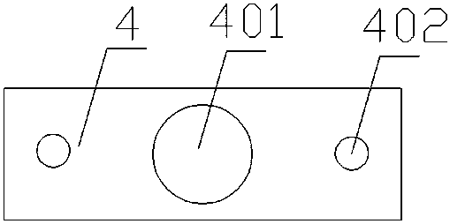
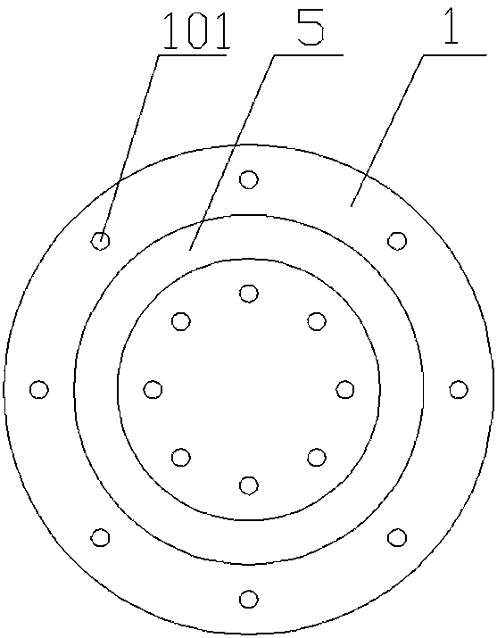
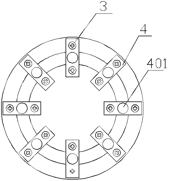
[0048] Such as image 3 and Figure 4As shown, the annular positioning groove 5 is preferably one, and its depth is 0.2 mm, and its width is 10.2 mm; the thickness of the selected substrate is 0.5 mm, and its diameter is 10 mm; the aperture of the sputtering through hole 401 in the center of the pressing sheet 4 is 9 mm; The thickness of the gasket 2 is 0.3 mm. The operation process is as follows:
[0049] Step 1. Take a pressing piece 4 and a screw 3, pass the screw 3 through the hard alloy pressing piece 4 and the washer 2 in turn, and connect it to the bottom plate 1, in a slightly loose state;
[0050] Step 2. Gently place the substrate in the groove on the bottom plate 1, and gently push the substrate from the side to the position corresponding to the bottom plate screw hole 101 described in step 1;
[0051] Step 3. Rotate the pressing piece 4, install the screw 3 on the other end of the pressing piece 4, press the pressing piece 4 lightly to ensure that the pressing p...
Embodiment 2
[0054] The thickness of the selected substrate is 0.2m, and the gasket 2 is not needed at this time. The operation process is as follows:
[0055] Step 1. Take a pressing piece 4, use a screw 3 to pass through the pressing screw hole 402 on one side of the pressing piece 4, and then screw it into the bottom plate screw hole 101;
[0056] Step 2, place the substrate in the annular positioning groove 5 on the bottom plate 1, and push the substrate from the side to the position corresponding to the bottom plate screw hole 101 described in step 1;
[0057] Step 3. Rotate the pressing piece 4, install the other end of the pressing piece 4 on the bottom plate 1 through the screw 3, and tighten the connected screw 3, so that the pressing piece 4 is in close contact with the substrate, and the contact surface is circular;
[0058] Step 4. Repeat steps 1 to 3 to install each substrate in turn.
Embodiment 3
[0060] When the thickness of the substrate is the same as the depth of the annular positioning groove 5, the pressing plate 4 with a baffle plate 6 can be used. The baffle plate 6 is arranged in the middle of the long side of the pressing plate 4, and there are two pieces whose width is smaller than the sputtering through hole. The diameter and height of 401 are equal to the depth of the annular positioning groove 5 , which can completely prevent the substrate from loosening and moving in the annular positioning groove 5 .
PUM
| Property | Measurement | Unit |
|---|---|---|
| thickness | aaaaa | aaaaa |
| diameter | aaaaa | aaaaa |
| thickness | aaaaa | aaaaa |
Abstract
Description
Claims
Application Information
 - R&D
- Intellectual Property
- Life Sciences
- Materials
- Tech Scout
- Unparalleled Data Quality
- Higher Quality Content
- 60% Fewer Hallucinations
Browse by: Latest US Patents, China's latest patents, Technical Efficacy Thesaurus, Application Domain, Technology Topic, Popular Technical Reports.
© 2025 PatSnap. All rights reserved.Legal|Privacy policy|Modern Slavery Act Transparency Statement|Sitemap|About US| Contact US: help@patsnap.com


