Mixing extruder with opposite internal and external spiral flutes and two coaxial screw rods
What is Al technical title?
Al technical title is built by PatSnap Al team. It summarizes the technical point description of the patent document.
A technology of external screw and internal screw, which is applied in the field of polymer material molding equipment, can solve the problems of serious scraping between the screw and the sleeve, scraping between the screw and the sleeve, and the impact on service life, so as to avoid processing difficulties and avoid mutual friction and wear, and the effect of improving the service life
Inactive Publication Date: 2017-01-04
SHUNDE POLYTECHNIC
View PDF5 Cites 2 Cited by
Summary
Abstract
Description
Claims
Application Information
AI Technical Summary
This helps you quickly interpret patents by identifying the three key elements:
Problems solved by technology
Method used
Benefits of technology
Problems solved by technology
[0004] Example 1, the patent "Coaxial Multi-screw Extruder" (publication number CN1059151C) discloses an extruder with multi-screw and multi-sleeve. The extruder described in this patent has two screws, two sleeve, but its two screw rods only have screw grooves on its outer circular surface, and its inner profile has no screw grooves, and its two sleeves have no screw grooves on its inner and outer circular surfaces. This patent The extruder is equipped with coaxial multi-layer barrels and screws, which can be used to extrude simultaneously wrapped multi-layer materials with different components. Severe grinding will affect the service life
[0005] Example 2, in the patent "composite co-extrusion conical screw extruder" (publication number CN201721024U), the barrel is equipped with two nested coaxial inner and outer screws. Although the inside of each screw is hollow, the screws have only outer There are no screw grooves on the inner surface, the structure is complex, the length of the required screw is long, the scraping between the screw and the sleeve is serious, and the service life is affected
Method used
Image
Click on the blue label to locate the original text in one second.
Reading with bidirectional positioning of images and text.
Examples
Embodiment Construction
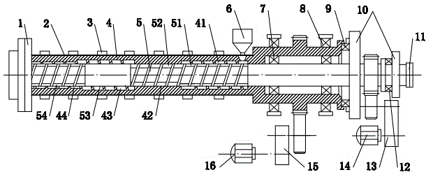
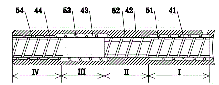
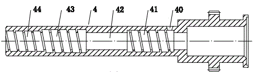
[0025] The specific embodiments of the present invention will be further described below in conjunction with the accompanying drawings. It should be noted here that the descriptions of these embodiments are used to help understand the present invention, but are not intended to limit the present invention. In addition, the technical features involved in the various embodiments of the present invention described below may be combined with each other as long as they do not constitute a conflict with each other.
[0026] In the description of the present invention, the orientations or positional relationships indicated by the terms "left" and "right" are based on the orientations or positional relationships shown in the drawings, which are only for the convenience of describing the present invention and do not require that the present invention must be based on a specific orientation. construction and operation, therefore, should not be construed as limiting the invention.
[002...
PUM
Abstract
The invention relates to a mixing extruder with opposite internal and external spiral flutes and two coaxial screw rods. The mixing extruder comprises a head, a thin-wall machine barrel, an electric heating ring, a hollow external screw rod, an internal screw rod, a hopper, a first radial bearing group, a second radial bearing group, a first thrust bearing, a second thrust bearing, a base, an electric rotating joint, a first transmission mechanism, a second transmission mechanism, a first motor and a second motor, wherein the electric heating ring sleeves the exterior of the thin-wall machine barrel; the thin-wall machine barrel sleeves the exterior of the hollow external screw rod; the hollow external screw rod sleeves the exterior of the internal screw rod; the hopper is arranged at the right end of the thin-wall machine barrel; the first motor drives the first transmission device to rotate, the first transmission device drives the internal screw rod to rotate; the second motor drives the second transmission device to rotate; the second transmission device drives the hollow external screw rod to rotate. The mixing extruder is characterized in that an internal spiral flute and an internal unthreaded hole are designed in the inner cavity of the hollow external screw rod; an external spiral flute and an external polished rod are designed at the external surface of the internal screw rod coaxial with the hollow external screw rod; the internal unthreaded hole and internal spiral flute of the hollow external screw rod and the external spiral flute and external polish rod of the internal screw rod form a material mixing, plastifying and conveying space. The mixing extruder has the advantages of enhanced mixing and plastifying, full mixing, good mass and heat transfer effect, high fusion capability, and high suitability for mixing, plastifying, extrusion and the like of multiple different materials.
Description
technical field [0001] The invention relates to a coaxial twin-screw mixing extruder with inner and outer opposite screw grooves, which is mainly used for mixing, plasticizing and extruding polymer materials, and belongs to the technical field of polymer material molding equipment. Background technique [0002] In petrochemical, rubber and plastic industries, mixing and extrusion molding machines are important equipment. After the polymer material enters the space of the screw groove through the hopper, it moves forward under the push of the screw edge, and the material in the screw groove has to pass through In a series of processes such as plasticizing and melting, its shape changes from an initial solid state to a molten state through many steps, and then it is processed into a finished product through extruder heads and other equipment. As the most important part of a plastic extrusion molding machine, the structure and shape of the screw not only affect the mixing and p...
Claims
Application Information
Patent Timeline
Application Date:The date an application was filed.
Publication Date:The date a patent or application was officially published.
First Publication Date:The earliest publication date of a patent with the same application number.
Issue Date:Publication date of the patent grant document.
PCT Entry Date:The Entry date of PCT National Phase.
Estimated Expiry Date:The statutory expiry date of a patent right according to the Patent Law, and it is the longest term of protection that the patent right can achieve without the termination of the patent right due to other reasons(Term extension factor has been taken into account ).
Invalid Date:Actual expiry date is based on effective date or publication date of legal transaction data of invalid patent.