
Extruder with multi-stage material extrusion channel

A technology for extruders and materials, applied in the field of extruders with multi-stage material extrusion channels, can solve the problems affecting the quality and efficiency of plasticizing extrusion, plasticizing performance, mixing capacity, grinding capacity and extrusion capacity Not strong, not very suitable for mixing and extrusion, etc., to achieve the effect of reducing axial force, strong mixing ability, and improving physical properties

Active Publication Date: 2017-04-19
湖南舜塑新材料科技有限公司
View PDF3 Cites 0 Cited by
  • Summary
  • Abstract
  • Description
  • Claims
  • Application Information

AI Technical Summary

Problems solved by technology

[0007] Although the above several conical screw extruders have overcome the shortcomings of ordinary screw extruders, they all have the problems of plasticizing performance, mixing ability, grinding ability and extrusion ability, which will eventually affect the plasticizing extrusion. output quality and efficiency
[0008] From the perspective of assembly relationship, in the above-mentioned patents, multiple conical screws are in meshing relationship and not coaxial, while in the Chinese patent "composite co-extrusion conical screw extruder", the two screws are coaxially assembled and To form an inner and outer set relationship, specifically, there are two nested inner and outer conical screws in the barrel, which can help to improve extrusion efficiency and quality, but it is mainly used for compound co-extrusion, not Very suitable for processing such as mixing and extrusion

Method used


Image

  • Extruder with multi-stage material extrusion channel
  • Extruder with multi-stage material extrusion channel
  • Extruder with multi-stage material extrusion channel

Examples


Embodiment Construction

[0032] The specific embodiments of the present invention will be further described below in conjunction with the accompanying drawings. It should be noted here that the descriptions of these embodiments are used to help understand the present invention, but are not intended to limit the present invention. In addition, the technical features involved in the various embodiments of the present invention described below may be combined with each other as long as they do not constitute a conflict with each other.

[0033] In the description of the present invention, the orientations or positional relationships indicated by the terms "left" and "right" are based on the orientations or positional relationships shown in the drawings, which are only for the convenience of describing the present invention and do not require that the present invention must be based on a specific orientation. construction and operation, therefore, should not be construed as limiting the invention.

[003...


PUM


Abstract

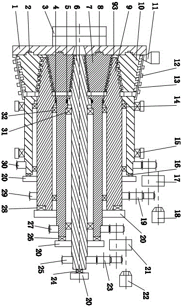
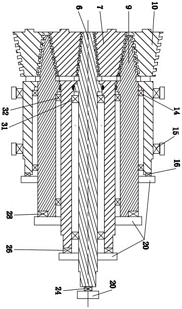
The present invention relates to an extruder with a multi-stage material extrusion channel, comprising a circular end panel, first and second end face heat-resistant sealing rings, an extruder head, first and second circumferential heat-resistant sealing rings, Central screw, first to third screw barrel, hopper, electric heating coil, machine barrel, first to fourth radial thrust bearing group, first to fourth thrust bearing, first and second transmission mechanism, first and second Two motors, the first and second transition gears, the base, and the first to fourth gears; the characteristic is that the left end of the central helical groove group of the central screw communicates with the central hole of the circular end panel, and the first inner helical groove group is connected with the central hole of the circular end panel. The central spiral groove group cooperates, the first outer spiral groove group cooperates with the second inner spiral groove group, the second outer spiral groove group cooperates with the third inner spiral groove group, the third outer spiral groove group cooperates with the inner hole of the barrel, and the second The left end of the three outer spiral groove groups communicates with the hopper. Its advantages are: the process of plasticizing, mixing and extruding is optimized, the quality of plasticized extruded products is improved and the efficiency is increased.

Description

technical field [0001] The invention and a device for plasticizing, crushing, kneading, extruding, and reacting extrusion of various inorganic and organic polymer materials, especially relate to an extruder with multi-stage material extrusion channels, belonging to The technical field of material crushing, mixing and extrusion molding equipment. Background technique [0002] In the fields of plastics, rubber and other industries, crushing, grinding, kneading and extrusion of materials are important processing methods and means. Ordinary screw extrusion devices have limited functions for crushing, shearing and grinding materials, especially when the materials are subjected to strong grinding and mixing, this shortcoming is even more prominent. [0003] In order to overcome the shortcomings of ordinary screw machines, some machines use conical screws. [0004] Chinese patent "conical screw plastic extruder", the screw is conical, and the closer to the discharge port, the den...

Claims


Application Information

Patent Timeline
Patent Type & Authority Patents(China)
IPC IPC(8): B29C47/36B29C48/525B29C48/385B29C48/425B29C48/49
CPCB29C48/375B29C48/525B29C48/425B29C48/49B29C48/385
Inventor 陈学锋凃明霞徐言生胡建国柯美元曾宪荣
Owner 湖南舜塑新材料科技有限公司
Learn More