
Method for welding outgoing line terminal of nuclear power half-speed turbine generator

A technology for turbogenerators and outgoing terminals, applied in welding equipment, arc welding equipment, manufacturing tools, etc., can solve the problem of affecting welding quality, affecting the manufacturing level of nuclear half-speed turbogenerators, and affecting the product quality and production of outgoing terminals Efficiency and other issues to achieve the effect of improving welding quality, reducing the chance of repair, and concentrating energy

Inactive Publication Date: 2017-01-04
HARBIN ELECTRIC MASCH CO LTD
View PDF7 Cites 2 Cited by
  • Summary
  • Abstract
  • Description
  • Claims
  • Application Information

AI Technical Summary

Problems solved by technology

Therefore, the welding process and welding parameters of the nuclear power half-speed turbo-generator outgoing terminal seriously affect the welding quality, which directly affects the quality and production efficiency of the outgoing terminal products, and also affects the manufacturing level of the nuclear power half-speed turbo-generator

Method used


Image

  • Method for welding outgoing line terminal of nuclear power half-speed turbine generator
  • Method for welding outgoing line terminal of nuclear power half-speed turbine generator

Examples


Embodiment 1

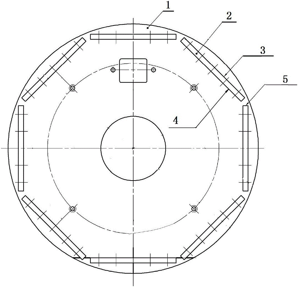
[0018] Embodiment 1: as figure 1 , figure 2 As shown, the welding method for the outlet terminals of nuclear power half-speed turbogenerators in this embodiment, the method is completed according to the following steps:

[0019] Step 1. Material preparation: the seat board 1 and the terminal board 2 are cut by plasma cutting, and the cutting is flattened by a hydraulic machine. The flattening process is protected by gaskets of the same material, and each single piece is processed to a qualified size;

[0020] Step 2, scribing: taking the center line of the seat plate 1 determined during the processing of step 1 as the reference, draw the assembly position line of the terminal plate 2 on the seat plate 1;

[0021] Step 3. Assembly: Assemble the terminal board (2) on the seat board 1 according to the assembly position line drawn in step 2. The distance from the terminal board 2 to the center of the seat board 1 is enlarged by 2~3mm according to the nominal size for assembly, a...

Embodiment 2

[0028] Embodiment 2: as figure 1 , figure 2 As shown, in step 7 of this embodiment, when welding the head weld 5, the local weld requires tungsten inert gas shielded welding TIG welding for end head welding, and the welding material is Φ2.5mm and the model is ERCuNi-7 Welding wire, welding current is 230A, welding voltage is 24V, shielding gas is more than 99.997% high-purity helium, gas flow rate is 14L / min. Other steps are the same as in Example 1.

Embodiment 3

[0029] Embodiment 3: The base plate 1 and the terminal plate 2 of this embodiment are copper plates whose material type is T2Y1. Other steps are identical with embodiment 1,2.


PUM


Abstract

The invention relates to a method for welding an outgoing line terminal of a nuclear power half-speed turbine generator. The method solves the problem of the prior art that since the process of manual metal-arc welding or gas shielded arc welding or the like is adopted for welding an outgoing line terminal, the welding deformation is serious, the welding size is difficult to guarantee, welding lines are difficult to form, the welding quality is poor and the welding is difficult in passing flaw detection at a single time. The method comprises the following steps: 1, preparing materials; 2, scribing; 3, assembling; 4, performing spot welding; 5, installing a tool fixture; 6, preheating before welding; 7, performing metal-inert gas welding (MIG) on a workpiece to be welded, wherein the welding current is 370-420A, the welding voltage is 24-34V, the welding speed is 350-500 mm / min, the protection gas is high-purity argon having the purity of more than 99.996%, and the flow rate of gas is 10-15 L / min; 8, performing modification welding; and 9, performing non-destructive inspection. The method is used for welding an outgoing line terminal of a nuclear power half-speed turbine generator.

Description

technical field [0001] The invention relates to a method for welding outlet terminals of nuclear power half-speed turbogenerators. Background technique [0002] The outlet terminal is the key structural part of the electrical connection of the nuclear power half-speed turbo-generator. The conventional 600,000-unit unit uses a whole piece of thick copper plate blanking and manufacturing through processing. However, the outlet terminals of nuclear power half-speed turbogenerators are welded with copper plates, the welds are difficult to fuse and the deformation after welding is serious, and defects such as pores and undercuts are prone to occur. In view of the complex structure of the outgoing terminal and the strict control of dimensional accuracy, its welding quality control has become one of the difficulties in the localization of millions of nuclear power plants. Therefore, the welding process and welding parameters of the nuclear power half-speed turbogenerator outgoing ...

Claims


Application Information

Patent Timeline
Patent Type & Authority Applications(China)
IPC IPC(8): B23P15/00B23P19/04B23K9/167B23K9/173
CPCB23P15/00B23K9/167B23K9/173B23P19/04
Inventor 田井成贾瑞燕邱希亮史文卿徐波娄红斌展中军石少强段伟赞
Owner HARBIN ELECTRIC MASCH CO LTD
Learn More