
Forming technological method for high-ferrum bearing ring with metal flow lines distributed along roller path

A metal streamline and forming process technology, applied to bearing components, shafts and bearings, mechanical equipment, etc., can solve the problems of low material utilization rate and metal streamline cannot be distributed, and achieve the effect of improving utilization rate

Active Publication Date: 2017-01-04
WUHAN UNIV OF TECH
View PDF6 Cites 2 Cited by
  • Summary
  • Abstract
  • Description
  • Claims
  • Application Information

AI Technical Summary

Problems solved by technology

This process cuts metal to form a raceway, resulting in low material utilization. After a large cutting allowance, the raceway of the high-speed iron tapered bearing ring cuts off the metal flow line, and the metal flow line cannot be distributed along the raceway.

Method used


Image

  • Forming technological method for high-ferrum bearing ring with metal flow lines distributed along roller path
  • Forming technological method for high-ferrum bearing ring with metal flow lines distributed along roller path
  • Forming technological method for high-ferrum bearing ring with metal flow lines distributed along roller path

Examples


Embodiment Construction

[0024] In order to have a clearer understanding of the technical features, purposes and effects of the present invention, the specific implementation manners of the present invention will now be described in detail with reference to the accompanying drawings.

[0025] Such as Figure 7 As shown, the process flow of the high-speed rail bearing ring forming process in which the metal flow lines are distributed along the raceway of the present invention is: pier thickening, blind hole punching, hot forging billet → ordinary hot-rolled near-conical outer ring and inner ring → precision close-shaped The hot-rolled high-speed rail bearing ring raceway profile forms metal streamlines distributed along the raceway (such as Figure 6a , Figure 6b shown) → deformation heat treatment → grindingsuperfinishing. Specifically include the following steps:

[0026] S1. After the ordinary hot-rolled near-conical outer ring and inner ring process, add a process of precision close-shaped h...


PUM


Abstract

The invention relates to a forming technological method for a high-ferrum bearing ring with metal flow lines distributed along a roller path. The method includes the following steps that S1, heading, blind hole punching and the like are used for hot forging so that a high-ferrum conical bearing ring blank can be manufactured, and then common hot rolling is conducted on a precision hot rolling mill to preset a near-shape conical high-ferrum conical bearing inner ring forged piece and an outer ring forged piece; S2, a roller mold is replaced on the precision hot rolling mill to perform precision near-shape hot rolling, a high-ferrum conical bearing ring roller path molded surface is formed, and accordingly an annular forged piece with the metal flow lines distributed along the roller path can be formed; S3, deformation heat treatment is immediately conducted on the precision hot rolling-formed high-ferrum bearing ring with the metal flow lines distributed along the roller path; and S4, the high-ferrum bearing ring subjected to hot rolling forming and deformation heat treatment is ground, ultra-precision subsequent machining is also performed, and accordingly the high-ferrum bearing ring piece with the required geometric accuracy can be obtained. By the adoption of the method, the high-ferrum bearing ring roller path can be formed directly, so that the metal flow lines are distributed along the roller path, and the phenomena that the material utilization rate is reduced due to high working allowance cutting and the metal flow lines are cut off through cutting machining are avoided.

Description

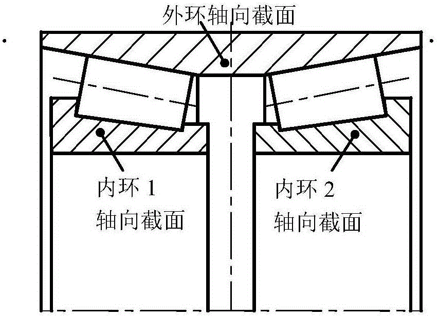
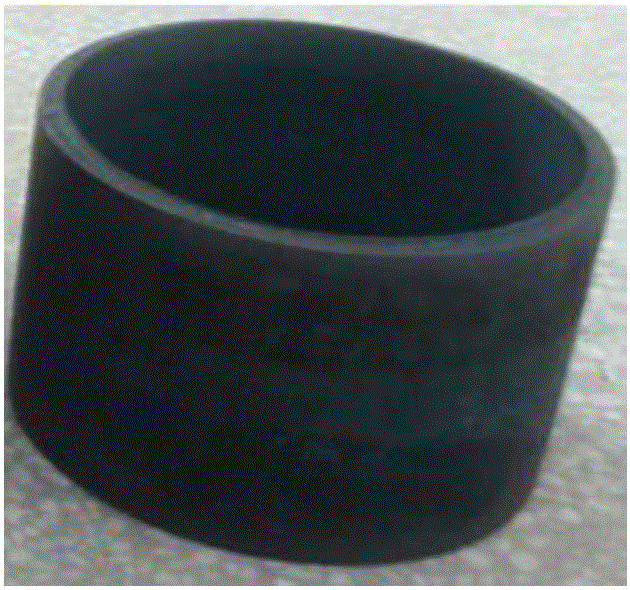
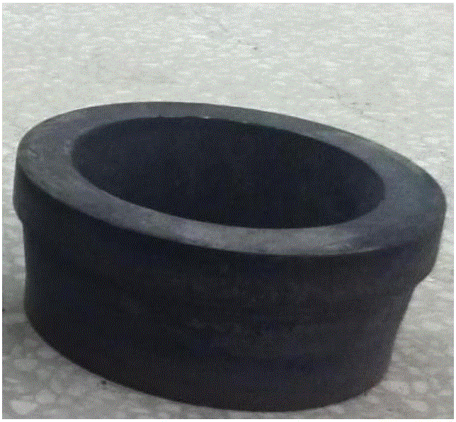
technical field [0001] The invention relates to the field of hot rolling forming, and more specifically relates to a high-speed rail bearing ring forming process method in which metal streamlines are distributed along raceways. Background technique [0002] High-speed rail tapered bearing inner ring (such as figure 1 As shown) the shape is asymmetrical in the axial direction, and there are steps at the large and small ends. The distribution of metal volume along the axial direction varies greatly, and the wall thickness varies greatly (the maximum wall thickness is 22.85mm, the minimum wall thickness is 10.15mm, and the wall thickness difference is 2 times. ). High-speed iron tapered bearing outer ring (such as figure 1 As shown) although the shape is symmetrical in the axial direction, the axial dimension is more than twice that of the conical inner ring, the distribution of metal volume along the axial direction varies greatly, and the wall thickness varies greatly (the ...

Claims


Application Information

Patent Timeline
Patent Type & Authority Applications(China)
IPC IPC(8): B23P15/00B21H1/12F16C33/58
CPCB21H1/12B23P15/00F16C33/58
Inventor 邓松华林
Owner WUHAN UNIV OF TECH
Learn More