Die cavity structure of back box body casing of wind power generating unit and method

A technology for wind turbines and rear boxes, which is applied in the casting field of castings, and can solve problems such as uneven filling, pore defects, and slag inclusion defects in castings

Active Publication Date: 2017-01-04
RIYUE HEAVY IND
View PDF7 Cites 5 Cited by
  • Summary
  • Abstract
  • Description
  • Claims
  • Application Information

AI Technical Summary

Problems solved by technology

The cavity structure of the FDM2 rear box generally includes the pouring system, the cavity of the rear box, and the air outlet set on the cavity of the rear box; the pouring system includes the sprue, the runner, and the runner passes through the transition runner. Feed iron into the cavity of the rear box body (that is, flow into molten iron); the above structure has the following disadvantages in the actual application process: due to the gravity of the molten iron itself, the molten iron that enters the sprue and runner in the early stage of pour

Method used


Image

  • Die cavity structure of back box body casing of wind power generating unit and method
  • Die cavity structure of back box body casing of wind power generating unit and method
  • Die cavity structure of back box body casing of wind power generating unit and method

Examples


Embodiment Construction

[0031] The new invention will be further described in detail below in conjunction with the accompanying drawings and specific embodiments; however, the following examples do not limit the present invention.

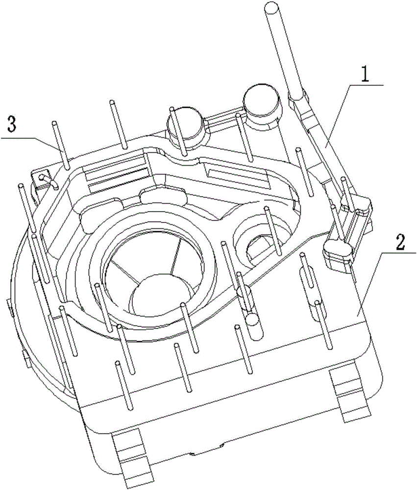
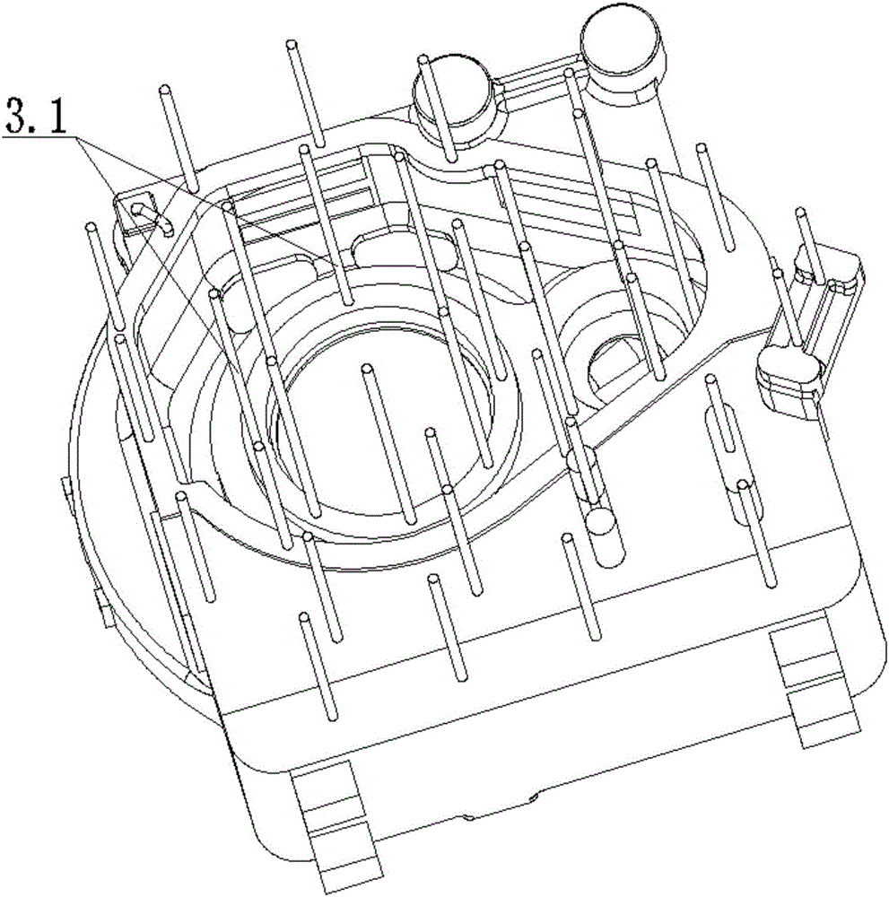
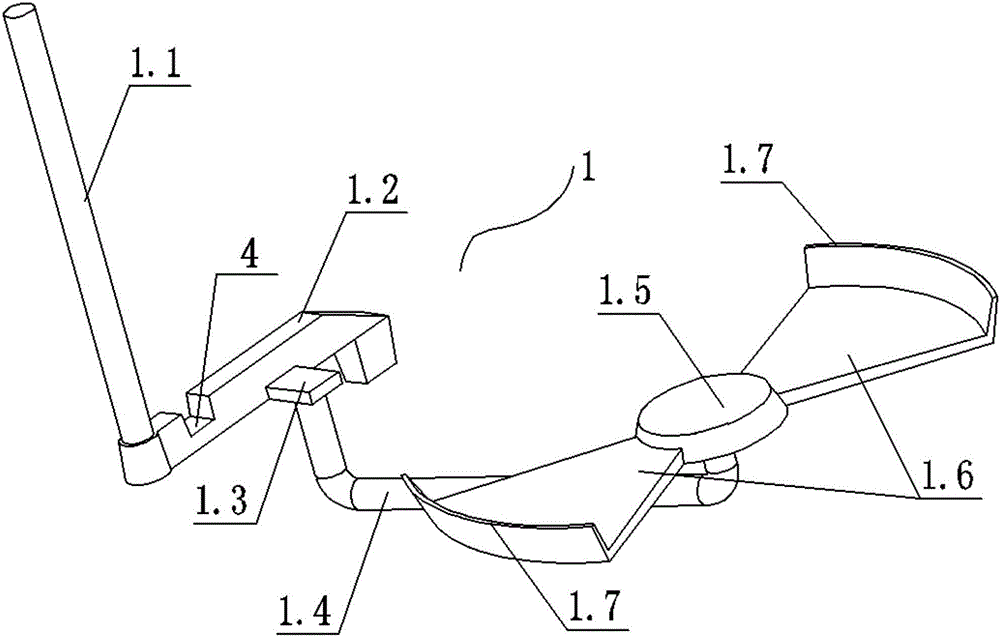
[0032] as attached Figure 1-3 As shown, as an embodiment: a cavity structure of a wind turbine rear box casting of the present invention, the structure includes a pouring system 1, a rear box cavity 2, and an air outlet 3 arranged on the rear box cavity The pouring system includes a sprue 1.1, a runner 1.2 connected with the sprue, and the runner is connected with a first transition runner 1.3, a second transition runner 1.4, and a third transition runner 1.5 in sequence. , the fourth transition runner 1.6; the fourth transition runner communicates with the rear box body cavity through the ingate 1.7; the first buffer runner 4 is arranged on the runner, and the cross-sectional area of ​​the sprue is the same as The cross-sectional area ratio of the first buffer runner i...


PUM


Abstract

The invention discloses a die cavity structure of a back box body casing of a wind power generating unit and a method. The structure comprises a casting system, a back box body die cavity and an air outlet opening, wherein the air outlet opening is formed in the back box body die cavity; the casting system comprises a sprue and a cross pouring gate communicating with the sprue; the cross pouring gate sequentially communicates with a first transition pouring gate, a second transition pouring gate, a third transition pouring gate and a fourth transition pouring gate; the fourth transition pouring gate communicates with the back box body die cavity through a flow gate; a first buffer pouring gate is arranged on the cross pouring gate; the ratio of the cross section area of the first buffer pouring gate to the cross section area of the sprue is 1:(0.60 to0.75). The die cavity structure has the advantages that the iron liquid mold filling instability and turbulence generated by the metal liquid in the casting process can be reduced; the quality stability of the casting can be improved; the slag inclusion defects and air hole defects are reduced; the high-quality requirements can be met.

Description

technical field [0001] The invention relates to the casting field of castings, in particular to a cavity structure of ductile iron castings and a method for preparing castings using the structure, that is, the cavity structure and method of a rear box casting of a wind power generating set. Background technique [0002] The gearbox of the wind turbine is an important component of the wind turbine. Its main function is to transmit the power generated by the fan blades under the action of the wind to the generator and obtain a corresponding speed. The reliability of the gearbox has a major impact on the safety of the unit, and the cost of failure recovery is also extremely expensive. It is understood that a major failure of the gearbox occurred in a 1.5MW unit designed to generate 2,200 hours a year. Nanjing High Accurate Transmission Equipment Manufacturing Group Co., Ltd. only The gear box equipment cost is between 1 million. If hoisting, transportation and labor costs are a...

Claims


Application Information

Patent Timeline
IPC IPC(8): B22C9/22B22C9/08C22C37/10C22C33/08
CPCB22C9/082B22C9/22C22C33/08C22C37/10
Inventor 宋贤发陈倩慧傅明康岳志强李凌羽黄志华
Owner RIYUE HEAVY IND
Why Eureka
Try Eureka