
Crankshaft and method of strengthening shaft component

A technology of shaft parts and crankshafts, applied in the directions of crankshafts, shafts and bearings, rotating parts resistant to centrifugal force, etc., can solve problems such as the decrease of relative bending moment strength, and achieve the effect of reducing tensile stress, restraining stretching, and avoiding processing

Active Publication Date: 2016-12-14
HONDA MOTOR CO LTD
View PDF7 Cites 5 Cited by
  • Summary
  • Abstract
  • Description
  • Claims
  • Application Information

AI Technical Summary

Problems solved by technology

Furthermore, there is a problem that tensile residual stress is generated in a portion adjacent to a portion to which compressive residual stress is applied by plastic working, and a portion where relative bending moment strength is lowered is generated.

Method used


Image

  • Crankshaft and method of strengthening shaft component
  • Crankshaft and method of strengthening shaft component
  • Crankshaft and method of strengthening shaft component

Examples


no. 2 Embodiment approach

[0055] refer to Figure 7 and Figure 8 A second embodiment of the present invention will be described.

[0056] Figure 7 The side view shapes of the first lower punch 121 and the second upper punch 132 are shown. A pressing surface 133 is formed on the lower surface of the second upper punch 132 . The pressing surface 133 has a molding section A consisting of a substantially cylindrical curved surface within a range of 45° on both sides of the circumferential direction from the direction of the normal line I (direction from the center of curvature O toward the center line of the second upper punch 132). , the substantially cylindrical curved surface has a radius of curvature obtained by subtracting the pressing amount from the radius of curvature of the cross section of the chamfered portion 15 . Here, the so-called “pressing amount” refers to the thickness of the pressing surface 133 processed along the normal line I to the chamfered portion 15 . In the molding section...


PUM


Abstract

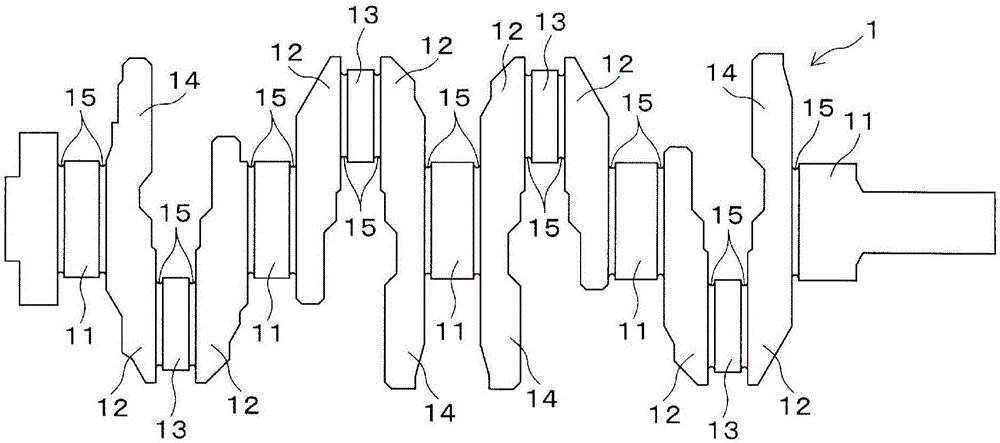
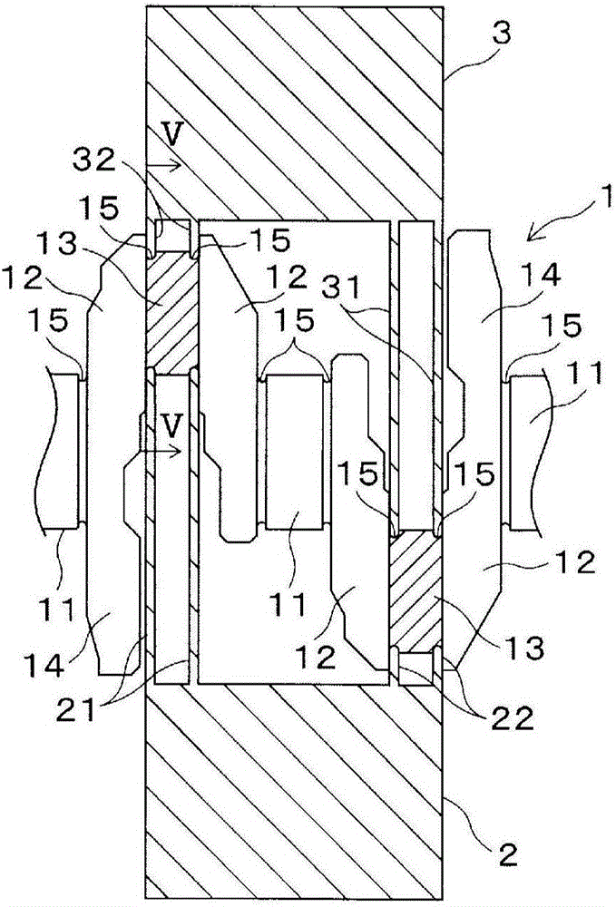
To provide a crankshaft which can be strengthened in a short time and which is strengthened over a wide range while avoiding wasteful processing as a matter of course. This crankshaft comprises a fillet portion (15) between a crank pin (13) and a journal pin (11). A compressive residual stress is applied in approximately equidistant ranges in both circumferential directions from the portion of the fillet (15) where the greatest bending load acts, which is the center position, and the processing depth for applying the compressive residual stress gradually reduces in the circumferential direction away from the center position where the compressive residual stress is greatest.

Description

technical field [0001] The present invention relates to a method of reinforcing a crankshaft and components having the shaft, and more particularly relates to a technique for reinforcing against bending load or torsional stress acting on a crank pin or a journal pin. Background technique [0002] For example, the crankshaft includes a journal pin and a crank pin, the large end of the connecting rod is rotatably supported by the crank pin, and the journal pin is rotatably supported by a journal bearing of the engine body. Grooves (chamfers) having semicircular cross-sections are formed at the corners of the crank pin and the journal pin in order to avoid collisions with counterpart components. The chamfered part is a part with low strength and receives a large bending moment when the internal combustion engine performs work. Therefore, it is desirable to strengthen the pin top of the chamfered part (in the case of an inline 4 cylinder, the positions where the phases are 0° an...

Claims


Application Information

Patent Timeline
Patent Type & Authority Applications(China)
IPC IPC(8): F16C3/08B21J5/02B21K1/08
CPCB21K1/08C21D7/04C21D9/30F16C3/08F16C2202/06F02B75/32
Inventor 田中利享三浦大介吉村拓郎竹内丰越野大介
Owner HONDA MOTOR CO LTD
Learn More