
A Multi-Focus Image Fusion Method Based on Decision Graph and Sparse Representation

A multi-focus image, sparse representation technology, applied in the field of image processing, can solve problems such as low applicability

Inactive Publication Date: 2019-09-27
NORTH CHINA ELECTRIC POWER UNIV (BAODING)
View PDF2 Cites 0 Cited by
  • Summary
  • Abstract
  • Description
  • Claims
  • Application Information

AI Technical Summary

Problems solved by technology

[0008] The purpose of the present invention is to propose a new multi-focus image fusion framework, that is, a multi-focus image fusion method based on decision graph and sparse representation, which can not only realize the fusion of multiple multi-focus images, but also improve the existing multi-focus image fusion The shortcomings of low applicability of the algorithm, and improving the quality of multi-focus fusion images

Method used


Image

  • A Multi-Focus Image Fusion Method Based on Decision Graph and Sparse Representation
  • A Multi-Focus Image Fusion Method Based on Decision Graph and Sparse Representation
  • A Multi-Focus Image Fusion Method Based on Decision Graph and Sparse Representation

Examples


Embodiment Construction

[0041] Specific embodiments of the present invention will be further described in detail below.

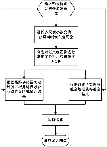
[0042] Such as figure 1 As shown, the present invention is a flow chart of a multi-focus image fusion method based on a decision graph and a sparse representation. First, two multi-focus images to be fused are input , , using the daub1 wavelet to decompose the two images once, and the obtained low-frequency sub-band image as a low-scale image corresponding to each multifocus image , .

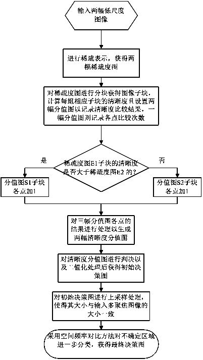
[0043] The next step is the process of final decision map generation. Such as figure 2 As shown in the flow chart of final decision-making diagram generation of the present invention:

[0044] Input parameters: low-scale images , ;

[0045] Output: final decision graph ;

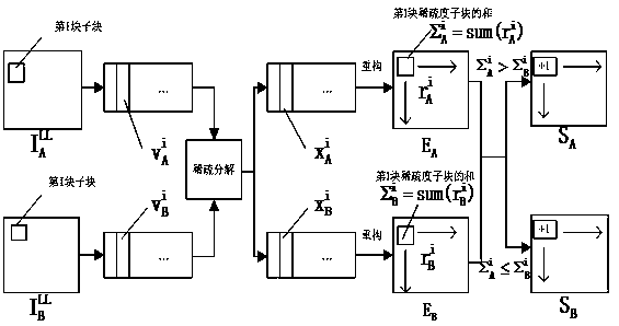
[0046] (1) Firstly, the over-complete sparse representation model is used to sparsely represent the two low-scale images to obtain their corresponding sparsity maps . The specific method is as follows: If ...


PUM


Abstract

The invention discloses a multi-focus image fusion method based on a decision graph and sparse representation. This method proposes a multi-focus image fusion framework different from previous multi-focus image fusion algorithms based on the characteristics of the human visual system. Analyze and study the transition area of ​​the image to avoid its influence on the fusion result and improve the quality of the fusion image. Implementation process: On the basis of sharpness analysis of low-scale images of multi-focus images, a decision map is generated, and the fusion result is obtained according to the decision map; considering that there is a deviation in the sharpness judgment of the transition area, it will lead to the generated decision map If there is an error, it is necessary to determine the transition area and process it with a multi-focus image fusion algorithm based on sparse representation to obtain the fusion result of the transition area; finally, the fusion result based on the decision map and the fusion result of the transition area are averaged to obtain the final fused image.

Description

technical field [0001] The invention belongs to the technical field of image processing, relates to image compression, image sparse representation, image space frequency comparison, mathematical morphology technology and image fusion technology, and can be used in the fields of machine vision, target recognition, clear imaging of digital cameras and the like. Background technique [0002] During the shooting process, when the focal length of the imaging system is set, due to the limitation of the depth of field of the lens, only the images formed by objects within a certain range before and after the conjugate front of the lens are clear, and the images formed by objects outside this range are clear. vague. When imaging a scene in practice, the resulting image is often not fully clear due to the different distances between the subject and the lens. In order to obtain a full clear image of the scene, a feasible method is to focus on each object in the scene separately, obtai...

Claims


Application Information

Patent Timeline
Patent Type & Authority Patents(China)
IPC IPC(8): G06T5/50G06T7/10G06K9/46G06T5/00
CPCG06T5/005G06T5/50G06T2207/20104G06T2207/20064G06V10/40G06V10/513
Inventor 廖斌磨唯
Owner NORTH CHINA ELECTRIC POWER UNIV (BAODING)
Learn More