Automatic pressure relief blowout preventer

An automatic venting and blowout preventer technology, which is applied in wellbore/well components, earthwork drilling, sealing/packing, etc., can solve problems such as hidden safety hazards in oil operations, and achieve the effect of preventing excessive pressure

Inactive Publication Date: 2016-12-14
YANCHENG JINRUI PETROLEUM MACHINERY CO LTD
View PDF0 Cites 2 Cited by
  • Summary
  • Abstract
  • Description
  • Claims
  • Application Information

AI Technical Summary

Problems solved by technology

[0002] In oil and gas exploration and development, if there is pressure in the well, it is necessary to install a sucker rod blowout preventer at the wellhead. After the existing sucker rod blowout preventer closes the wellhead, once the pressure in the well is higher than the blowout preventer When the rated pressure is exceeded, it will bring great safety hazards to oil operations

Method used


Image

  • Automatic pressure relief blowout preventer
  • Automatic pressure relief blowout preventer

Examples


Embodiment Construction

[0010] The specific content of the present invention will be described in detail below in conjunction with the accompanying drawings and specific embodiments.

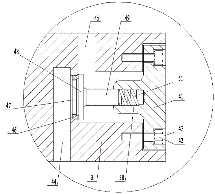
[0011] like figure 1 , figure 2 As shown, the automatic pressure relief blowout preventer includes: a casing 1, side doors 2 arranged on both sides of the casing 1, and a gate 3 arranged in the side door 2, and an automatic pressure relief device is arranged in one of the gates 3 4. The structure of the automatic pressure relief device 4 includes: a valve cover 41 arranged on one side of the gate plate 3, the valve cover 41 is fixed in the gate plate 3 by countersunk screws 42, and on the valve cover 41 A countersunk hole 43 that cooperates with the countersunk head screw 42 is provided, and an inlet channel 44 and an outlet channel 45 are arranged in the gate plate 3 .

[0012] A valve seat 46 is provided on the gate plate 3 at the upper end of the inlet channel 44, and a connecting channel 47 communicating with th...


PUM


Abstract

The invention discloses an automatic pressure relief blowout preventer which comprises a shell, side doors and gate segments. The side doors are arranged on two sides of the shell, the gate segments are arranged in the side doors, an automatic pressure relief device is arranged in one of the gate segments and structurally comprises a bonnet, the bonnet is arranged in a side of the corresponding gate segment and is fixed into the gate segment by the aid of countersunk head screws, countersunk head holes which are matched with the countersunk head screws are formed in the bonnet, an inlet channel and an outlet channel are arranged in the gate segment, a valve seat is arranged on the gate segment and is positioned on a side of the upper end of the inlet channel, a connecting channel which is communicated with the inlet channel is arranged in the valve seat, a valve clack which is matched with the valve seat is arranged in the gate segment and is connected with one end of a valve stem, a slide cavity is arranged in the bonnet, the other end of the valve stem is slidably arranged in the slide cavity, and a pressure spring is arranged in the slide cavity. The automatic pressure relief blowout preventer has the advantage that the automatic pressure relief blowout preventer is safe in use.

Description

technical field [0001] The invention relates to a ram blowout preventer used in the oil and gas development process. Background technique [0002] In oil and gas exploration and development, if there is pressure in the well, it is necessary to install a sucker rod blowout preventer at the wellhead. After the existing sucker rod blowout preventer closes the wellhead, once the pressure in the well is higher than the blowout preventer When the rated pressure is exceeded, it will bring great safety hazards to oil operations. Contents of the invention [0003] The technical problem to be solved by the present invention is to provide a safe automatic pressure relief blowout preventer. [0004] In order to solve the above-mentioned technical problems, the technical solution adopted by the present invention is: the automatic pressure relief blowout preventer, including: the casing, the side doors arranged on both sides of the casing and the rams arranged in the side doors, and on...

Claims


Application Information

Patent Timeline
Patent Type & Authority Applications(China)
IPC IPC(8): E21B33/06E21B34/02
CPCE21B33/06E21B34/02
Inventor 花金年
Owner YANCHENG JINRUI PETROLEUM MACHINERY CO LTD
Why Eureka
Try Eureka