
Semiconductor microwave heating device

A microwave heating device and semiconductor technology, applied in microwave heating, electric heating devices, electric/magnetic/electromagnetic heating, etc., can solve the problems of burning microwave sources, insufficient energy, and high microwave power

Active Publication Date: 2016-12-07
GUANGDONG MIDEA KITCHEN APPLIANCES MFG CO LTD +1
View PDF6 Cites 3 Cited by
  • Summary
  • Abstract
  • Description
  • Claims
  • Application Information

AI Technical Summary

Problems solved by technology

[0003] One feed port corresponds to one antenna, and multiple feed ports have multiple antennas. The antenna emits the microwaves generated and amplified by the microwave source, which can be transmitted to the cavity through a waveguide or without a waveguide. Theoretically speaking, the antenna has good radiation Microwave capability, it also has a good ability to absorb microwaves, that is to say, if the multi-channel semiconductor microwave heating equipment is not well designed, there will be situations where the channels emit and absorb microwave power from each other. The disadvantages caused by this are first It is because the energy obtained by the object to be heated is not enough. In severe cases, one channel will absorb the microwave power of other channels. If the microwave power is too high, the corresponding microwave source will be burned

Method used


Image

  • Semiconductor microwave heating device
  • Semiconductor microwave heating device
  • Semiconductor microwave heating device

Examples


Embodiment Construction

[0034] Embodiments of the present invention are described in detail below, examples of which are shown in the drawings, wherein the same or similar reference numerals denote the same or similar elements or elements having the same or similar functions throughout. The embodiments described below by referring to the figures are exemplary only for explaining the present invention and should not be construed as limiting the present invention.

[0035] In the description of the present invention, it should be understood that the terms "first" and "second" are used for description purposes only, and cannot be interpreted as indicating or implying relative importance or implicitly indicating the quantity of indicated technical features. Thus, a feature defined as "first" or "second" may explicitly or implicitly include one or more of said features. In the description of the present invention, "plurality" means two or more, unless otherwise specifically defined.

[0036] In the descr...


PUM


Abstract

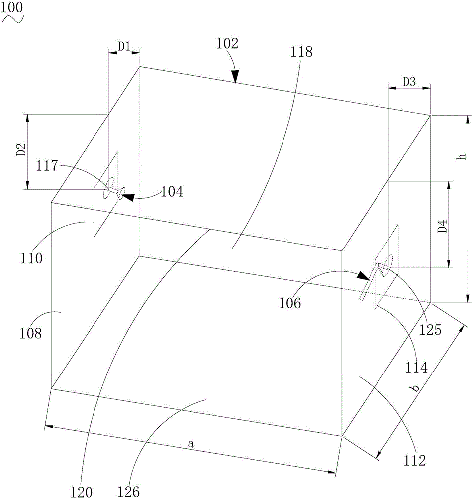
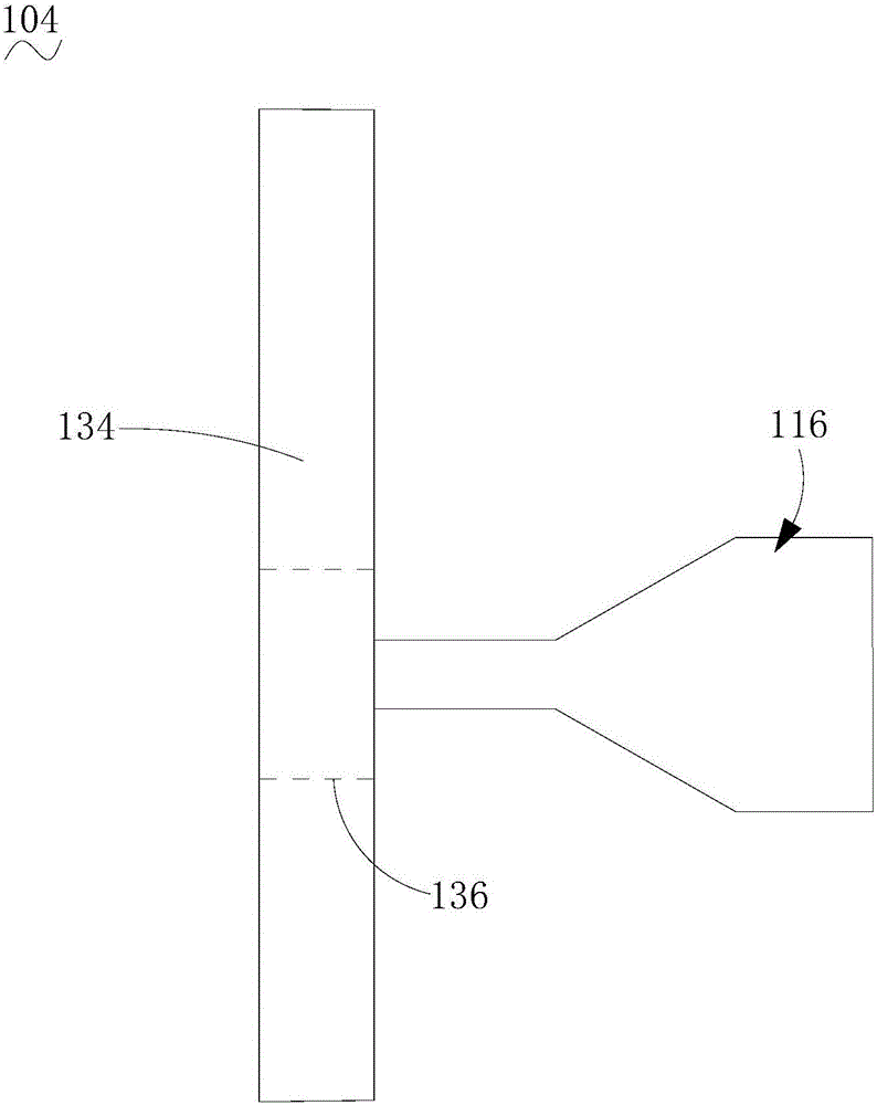
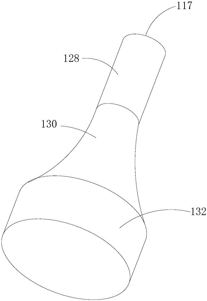
The invention discloses a semiconductor microwave heating device. The device comprises a cuboid cavity. The length of the cavity is 300mm to 360mm, the width 220mm to 280mm, and the height 66mm to 126mm. A first feeding inlet is disposed on the left sidewall of the cavity, and a right feeding inlet is disposed on the right sidewall of the cavity. The first feeding inlet is provided with a first antenna. The distance between the circle enter of the feeding end of the first antenna rod of the first antenna and the back side of the cavity is 68mm to 78mm, and the distance between the circle enter of the feeding end of the first antenna rod of the first antenna and the top surface of the cavity is 40mm to 50mm. The first antenna rod is conical. The second feeding inlet is provided with a second antenna. The second antenna rod of the second antenna is vertically connected to the third antenna rod of the second antenna. The distance between the center of circle of the feeding end of the second antenna rod and the back side of the cavity is 145mm to 155mm, and the distance between the center of circle of the feeding end of the second antenna rod and the top surface of the cavity is 55mm to 65mm. The third antenna rod is parallel to the bottom surface of the cavity and points towards the front panel of the cavity. The semiconductor microwave heating device meets the above-mentioned conditions, so as to obtain better standing wave values at the two feeding inlets. The isolation degree of the first antenna and the second antenna meets the design requirements.

Description

technical field [0001] The invention relates to the technical field of household appliances, and more specifically, to a semiconductor microwave heating device. Background technique [0002] In related technologies, semiconductor microwave heating technology continues to develop. In order to improve heating performance, such as heating efficiency and heating uniformity, everyone began to study multi-channel semiconductor microwave heating (microwaves are fed into the cavity from multiple feeding ports), and multi-channel Microwave heating can make the heating more uniform, and can also avoid the phenomenon of ignition of the feed port caused by feeding high power from one feed port. [0003] One feed port corresponds to one antenna, and multiple feed ports have multiple antennas. The antenna emits the microwaves generated and amplified by the microwave source, which can be transmitted to the cavity through a waveguide or without a waveguide. Theoretically speaking, the anten...

Claims


Application Information

Patent Timeline
Patent Type & Authority Applications(China)
IPC IPC(8): H05B6/64
CPCH05B6/64H05B6/686H05B6/72
Inventor 张斐娜孙宁刘民勇刘建伟夏然王轩贾逾泽史龙
Owner GUANGDONG MIDEA KITCHEN APPLIANCES MFG CO LTD
Learn More