
A decentralized hybrid energy storage and power compensation system based on mmc topology

A hybrid energy storage and compensation system technology, which is applied in the storage of electric energy systems, reactive power compensation, reactive power adjustment/elimination/compensation, etc., can solve problems such as incomplete controllability, instability, and stability problems

Active Publication Date: 2019-05-31
ZHEJIANG UNIV
View PDF4 Cites 0 Cited by
  • Summary
  • Abstract
  • Description
  • Claims
  • Application Information

AI Technical Summary

Problems solved by technology

After distributed generation is connected to the grid, its instability and incomplete controllability will lead to serious power quality problems, stability problems and safe operation problems in the power system

Method used


Image

  • A decentralized hybrid energy storage and power compensation system based on mmc topology
  • A decentralized hybrid energy storage and power compensation system based on mmc topology
  • A decentralized hybrid energy storage and power compensation system based on mmc topology

Examples


Embodiment 1

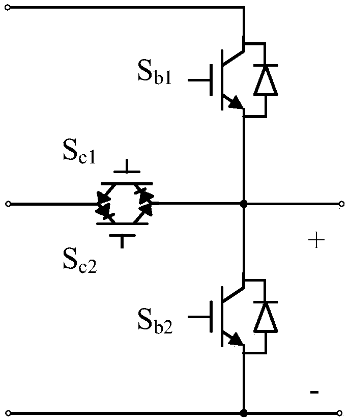
[0051] Such as Image 6 As shown, the distributed hybrid energy storage and power compensation system based on the MMC topology adopts a single star topology, and the converter and sub-modules are connected in series in the circuit, and the sub-modules are sub-modules with a T-shaped module structure.

[0052] The dielectric energy storage part of the sub-module adopts a lead storage battery and a supercapacitor.

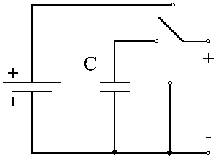
[0053] The T-shaped module structure can be equivalent to a single-pole three-throw switch, and its principle topology is as follows: figure 1 As shown, the topology can be understood as a combination of a single-pole three-throw switch, a lead-acid battery, and a supercapacitor.

[0054] The sub-module of the T-shaped module structure is an equivalent single-pole three-throw switch composed of four power switches, which controls the components connected to the circuit at any time, and can choose lead-acid battery connection, super capacitor connection or bypass. ...

Embodiment 2

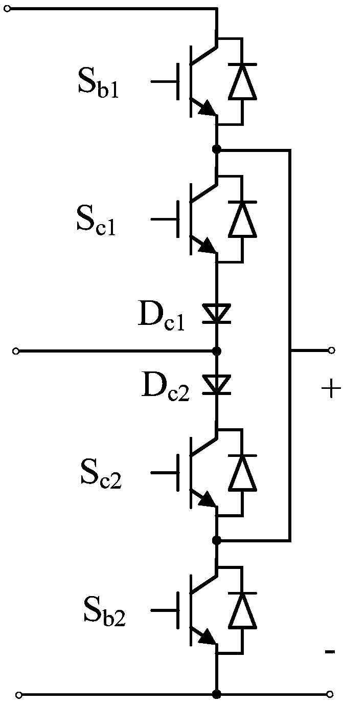
[0063] Such as Image 6 As shown, the distributed hybrid energy storage and power compensation system based on the MMC topology adopts a single star topology, and the converter and sub-modules are connected in series in the circuit, and the sub-modules are sub-modules of the bridge arm module structure.

[0064] The dielectric energy storage part of the sub-module of the bridge arm module structure adopts a lithium battery and a super capacitor.

[0065] The bridge arm module structure can be equivalent to a single-pole three-throw switch, and its principle topology is as follows: figure 1 As shown, the topology can be understood as a combination of a single-pole three-throw switch, a lithium battery, and a supercapacitor.

[0066] Such as figure 2 As shown, in the power stage part of the bridge arm module structure, the IGBT S c1 Collector and IGBT S b1 Emitter, IGBT S c2 Emitter, IGBT S b2 Collector connected; IGBT S c1 emitter and diode D c1 anode connected, the di...


PUM


Abstract

The invention discloses an MMC topology-based distributed hybrid energy storage and power compensation system. A single-star topological structure is adopted; sub-modules comprise energy storage medium parts and power level parts; each energy storage medium part comprises at least one energy storage battery and a capacitor; the batteries and the capacitors are connected to a main circuit loop through power-level different ports; and each power level part comprises a bridge arm module structure or a T-shaped module structure comprising power switches and power diodes. By the system, a high-current power reactor does not need to be used on the basis of not significantly increasing the number of the sub-modules; the power levels of the sub-modules are multiplexed; two kinds of energy storage mediums of the energy storage batteries and the capacitors are dispersedly distributed into various sub-modules to facilitate power balance on various energy storage mediums; and cooperative work of multiple mediums is conducive to technological economy consideration and optimization of an energy storage technology in multiple dimensions of the lifetime, the response speed, the conversion efficiency and the like.

Description

technical field [0001] The invention belongs to the technical field of power electronic systems, and in particular relates to a distributed hybrid energy storage and power compensation system based on MMC topology. Background technique [0002] With the development and popularization of distributed new energy technology, the power system gradually shows the trend of topology network and decentralization of power supply and load. This requires mature and advanced power electronic AC compensation equipment to ensure system safety, stability and performance. [0003] Distributed power generation methods such as wind energy and solar energy are greatly affected by the environment and climate, and the output power is unstable and not fully controllable. However, in the traditional concept of the power system, electric energy is used immediately and cannot be stored. It must be consumed in a timely manner, and the power generated by the load and the power consumed by the load mus...

Claims


Application Information

Patent Timeline
Patent Type & Authority Patents(China)
IPC IPC(8): H02J15/00H02J3/18
CPCY02E40/30
Inventor 邓焰林逸铭王昆李广地
Owner ZHEJIANG UNIV
Learn More