Structure laser with support barrel

A technology for supporting cylinders and lasers, applied in the field of lasers, can solve the problems of reduced alignment accuracy of output mirrors and reflective mirrors, reduced laser service life, unreliability, etc., to improve reliability and service life, and reduce the risk of relative slippage , to ensure the effect of positive alignment accuracy

Active Publication Date: 2016-12-07
CHENGDU WEESON TECH
View PDF4 Cites 1 Cited by
  • Summary
  • Abstract
  • Description
  • Claims
  • Application Information

AI Technical Summary

Problems solved by technology

[0006] However, with further in-depth research, the inventor found that the support frame of the current structure still has deficiencies, specifically: firstly, the discharge tube can be well supported in the direction along the legs, but between the legs However, the part between them cannot be well supported, and during the process of transportation, the impact on the laser may come from any direction, so this kind of support is actually not reliable; on the other hand, during the working process of the laser, As the working time increases, the temperature of the laser rises, causing a certain amount of deformation in the radial and axial directions of the laser. However, the temperature growth among the discharge tube, water-cooled tube and gas storage tube is not consistent. Therefore, in the laser When thermal deformation occurs, the support frame will have a certain amount of sliding between the gas storage tube and the water cooling tube, which is very easy to scratch the gas storage tube and water cooling tube, reducing the service life of the laser; The support frame is close to the water cooling tube and the air storage tube. When the support frame does not slide, it will constrain the thermal deformation of the water cooling tube and the air storage tube in the axial direction, reducing the coaxiality of the water cooling tube and the air storage tube, resulting in the output lens and Reduced alignment accuracy of reflective mirrors reduces laser beam quality

Method used


Image

  • Structure laser with support barrel
  • Structure laser with support barrel
  • Structure laser with support barrel

Examples


Embodiment Construction

[0051] Below in conjunction with accompanying drawing, the present invention is described in detail.

[0052] In order to make the object, technical solution and advantages of the present invention clearer, the present invention will be further described in detail below in conjunction with the accompanying drawings and embodiments. It should be understood that the specific embodiments described here are only used to explain the present invention, not to limit the present invention.

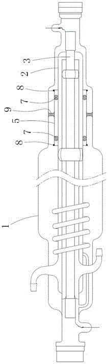
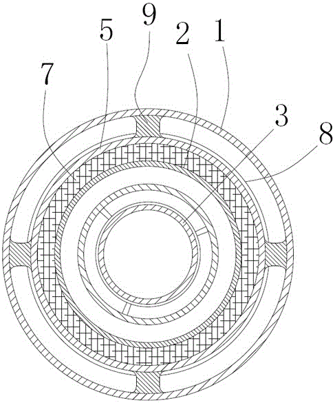
[0053] Such as Figure 1-4 As shown, the example:

[0054] A laser with a support tube structure, comprising a gas storage tube 1, a water-cooled tube 2 and a discharge tube 3, one end of the gas storage tube 1 is provided with a reflective lens, the other end of the gas storage tube 1 is provided with an output lens, the water-cooled The tube 2 is sleeved in the gas storage tube 1, the discharge tube 3 is sleeved in the water-cooled tube 2, the two ends of the water-cooled tube 2 are respective...


PUM


Abstract

The invention relates to the field of lasers, in particular to a structure laser with a support barrel. The laser comprises a reservoir pipe, a water-cooling pipe and a discharge tube, wherein a reflecting lens is arranged at one end of the reservoir pipe and an output lens is arranged at the other end of the reservoir pipe; the water-cooling pipe is sleeved with the reservoir pipe; the discharge tube is sleeved with the water-cooling pipe; two ends of the water-cooling pipe and the discharge tube are in closed connection separately; and a support barrel structure sleeves outside the water-cooling pipe and elastically supports the water-cooling pipe in the water-cooling pipe. By the laser, on one hand, the direct alignment accuracy of the reflecting lens and the output lens is ensured to improve the output quality of a laser beam; and on the other hand, the risk of relative slippage between a support part and the water-cooling pipe and the discharge tube is reduced to reduce the risk that the reservoir pipe and the water-cooling pipe are scratched by the support part is reduced. Therefore, the reliability of the laser is improved and the service lifetime is prolonged.

Description

technical field [0001] The invention relates to the field of lasers, in particular to a laser with a support cylinder structure. Background technique [0002] Due to the relatively large power and relatively high energy conversion efficiency of carbon dioxide lasers, the spectral lines are relatively rich, and there are dozens of spectral lines near 10 microns. The laser output has been widely used in industry, military, medical, scientific research, etc. Applications. [0003] The current carbon dioxide laser usually includes a discharge tube, a water-cooled tube set outside the discharge tube, a gas storage tube set outside the water-cooled tube, electrodes arranged at both ends of the discharge tube, and output windows and reflectors set at both ends of the gas storage tube. Window, the reflective window includes reflective mirror and reflective mirror cooling device, the output window includes output mirror and output mirror cooling device, and the discharge tube is fil...

Claims


Application Information

Patent Timeline
Patent Type & Authority Applications(China)
IPC IPC(8): H01S3/02H01S3/041H01S3/101
CPCH01S3/02H01S3/041H01S3/101
Inventor 殷卫援
Owner CHENGDU WEESON TECH
Why Eureka
Try Eureka