Time measurement circuit and optoelectronic range finder using such a time measurement circuit

A technology of time measurement and range finder, which is applied in the direction of measuring the change of electric quantity/magnetism proportional to the change of time, measuring device, re-radiation of electromagnetic waves, etc., which can solve the problem of insufficient accuracy in determining the running time Correctly detect and other issues

Active Publication Date: 2016-12-07
HEXAGON TECH CENT GMBH
View PDF9 Cites 31 Cited by
  • Summary
  • Abstract
  • Description
  • Claims
  • Application Information

AI Technical Summary

Problems solved by technology

At close range, the signal can saturate the receiver so that the shape of the transmitted signal is no longer correctly ascertained and the elapsed time is determined with insufficient accuracy

Method used


Image

  • Time measurement circuit and optoelectronic range finder using such a time measurement circuit
  • Time measurement circuit and optoelectronic range finder using such a time measurement circuit
  • Time measurement circuit and optoelectronic range finder using such a time measurement circuit

Examples


Embodiment Construction

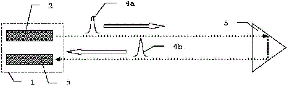
[0091] Figure 1a A schematic illustration of a prior art optoelectronic distance measuring device 1 according to the pulse runtime principle is shown. A transmitter 2 and a receiver 3 are arranged in the distance measuring device 1 . The transmitter 2 emits a light pulse 4a which is again detected by the receiver 3 as a backscattered light pulse 4b after being reflected or backscattered on a target (eg retroreflector 5) 4a. Instead of individual light pulses, it is also possible according to the invention to use analogue or digitally coded pulse sequences or continuously modulated transmission signals.

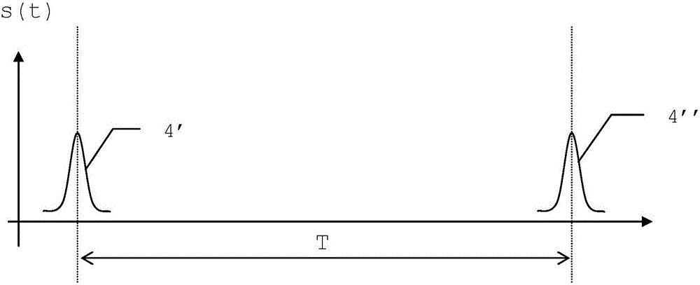
[0092] Such as Figure 1b As illustrated in the schematic illustration, the distance is determined according to the running time T of the chronological difference between the point in time of the start of the emitted light pulse 4' and the time of reception of the backscattered light pulse 4". In this case, The determination of the point in time of reception is performed by...


PUM


Abstract

The invention relates to a time measurement circuit and an optoelectronic range finder using such a time measurement circuit. The time measurement circuit and for an incoming signal, in such a condition, has a comparator stage for generating a comparator output signal depending on a fulfillment of a criterion by the incoming signal, wherein exceeding or falling below a threshold value is defined as the criterion. Furthermore, a digitization stage is provided, for sampling, which is performed at a defined sampling rate, of an input signal fed to the digitization stage and converting it into digital data containing sampled values for the input signal, and an evaluation unit for determining a chronological location for the incoming signal by evaluating the digital data. A signal generating stage is interconnected between the comparator stage and the digitization stage, which is designed to generate and output, in a chronologically fixed manner dependent on the content of the comparator output signal, a shape signal, which is designed for post-sampling interpolation ability, of known shape. The evaluation unit then determines the time for the incoming analog signal while using a chronological interpolation of the values contained in the digital data and the known shape of the shape signal.

Description

technical field [0001] The present invention relates to a time measuring circuit and a photoelectric distance meter having such a time measuring circuit. Background technique [0002] Various principles and methods for determining a desired distance are known in the field of optical and / or optoelectronic distance measurement. One method is to emit pulses of electromagnetic radiation, such as a laser, towards an object to be measured, and then receive echoes from this object as backscattering objects, wherein the distance to the object to be measured can be determined based on the elapsed time of the pulses . Such pulsed time-of-flight testers (ToF, ie time-of-flight) are widespread as standard solutions in many fields. [0003] Two different schemes are used to detect return pulses. [0004] In the so-called threshold method, a light pulse is detected when the intensity of the radiation incident on the detector of the rangefinder used exceeds a certain threshold, where th...

Claims


Application Information

Patent Timeline
Patent Type & Authority Applications(China)
IPC IPC(8): G01S17/10G01S7/4865G01S17/894
CPCG01S17/10G01S7/4865G01S17/894G01S17/08G04F10/10
Inventor 雷托·施图茨S·贝斯特勒R·沃尔格南特J·辛德林
Owner HEXAGON TECH CENT GMBH
Why Eureka
Try Eureka