A positioning and axial force testing device for a non-thrust bearing rotor

A testing device, thrust bearing technology, applied in bearing-related force sensors, measuring devices, force/torque/work measuring instruments, etc. Small mass of the follower shaft, simple and convenient assembly, and strong adaptability

Active Publication Date: 2019-01-18
AECC SHENYANG ENGINE RES INST
View PDF7 Cites 0 Cited by
  • Summary
  • Abstract
  • Description
  • Claims
  • Application Information

AI Technical Summary

Problems solved by technology

For example, the modification of the tester is not only expensive, but also has a narrow scope of application, low frequency of use, and inconvenient installation

Method used


Image

  • A positioning and axial force testing device for a non-thrust bearing rotor
  • A positioning and axial force testing device for a non-thrust bearing rotor
  • A positioning and axial force testing device for a non-thrust bearing rotor

Examples


Embodiment Construction

[0022] In order to make the objectives, technical solutions and advantages of the present invention clearer, the technical solutions in the embodiments of the present invention will be described in more detail below in conjunction with the drawings in the embodiments of the present invention. In the drawings, the same or similar reference numerals denote the same or similar elements or elements having the same or similar functions throughout. The described embodiments are some, but not all, embodiments of the invention. The embodiments described below by referring to the figures are exemplary and are intended to explain the present invention and should not be construed as limiting the present invention. Based on the embodiments of the present invention, all other embodiments obtained by persons of ordinary skill in the art without creative efforts fall within the protection scope of the present invention. Embodiments of the present invention will be described in detail below ...


PUM


Abstract

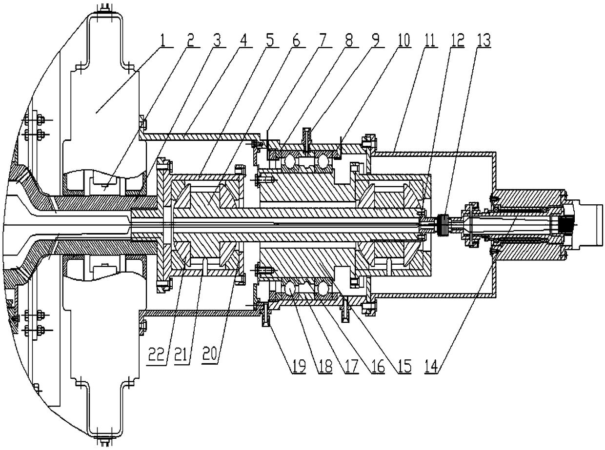
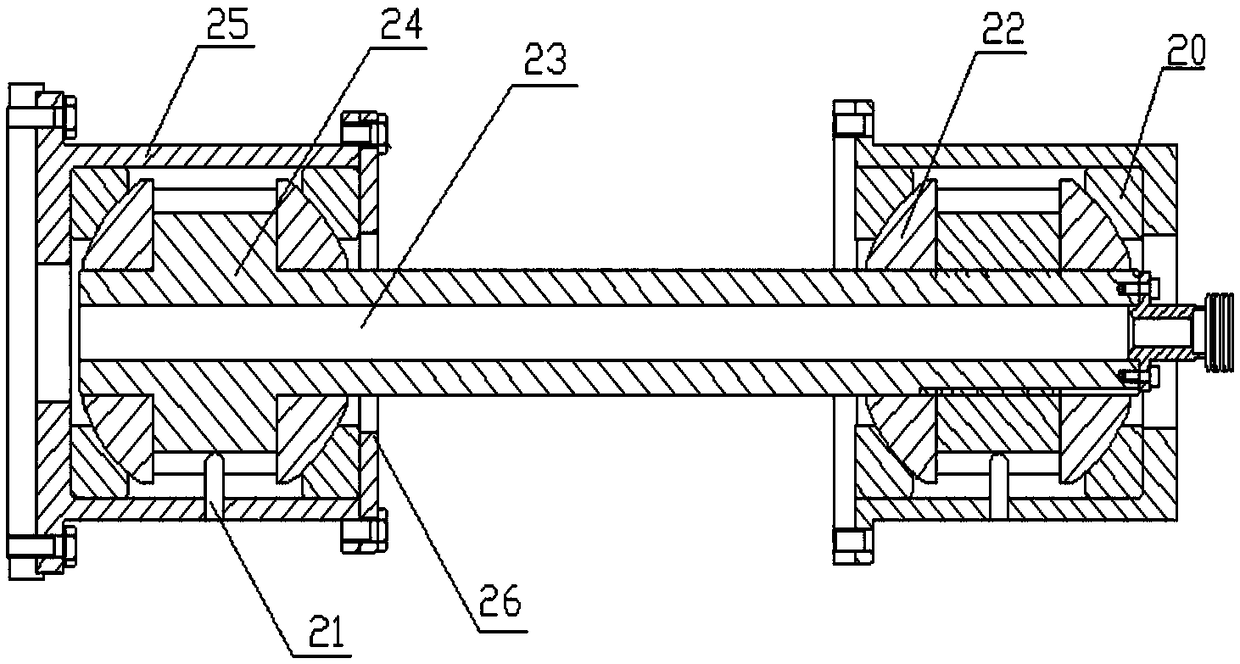
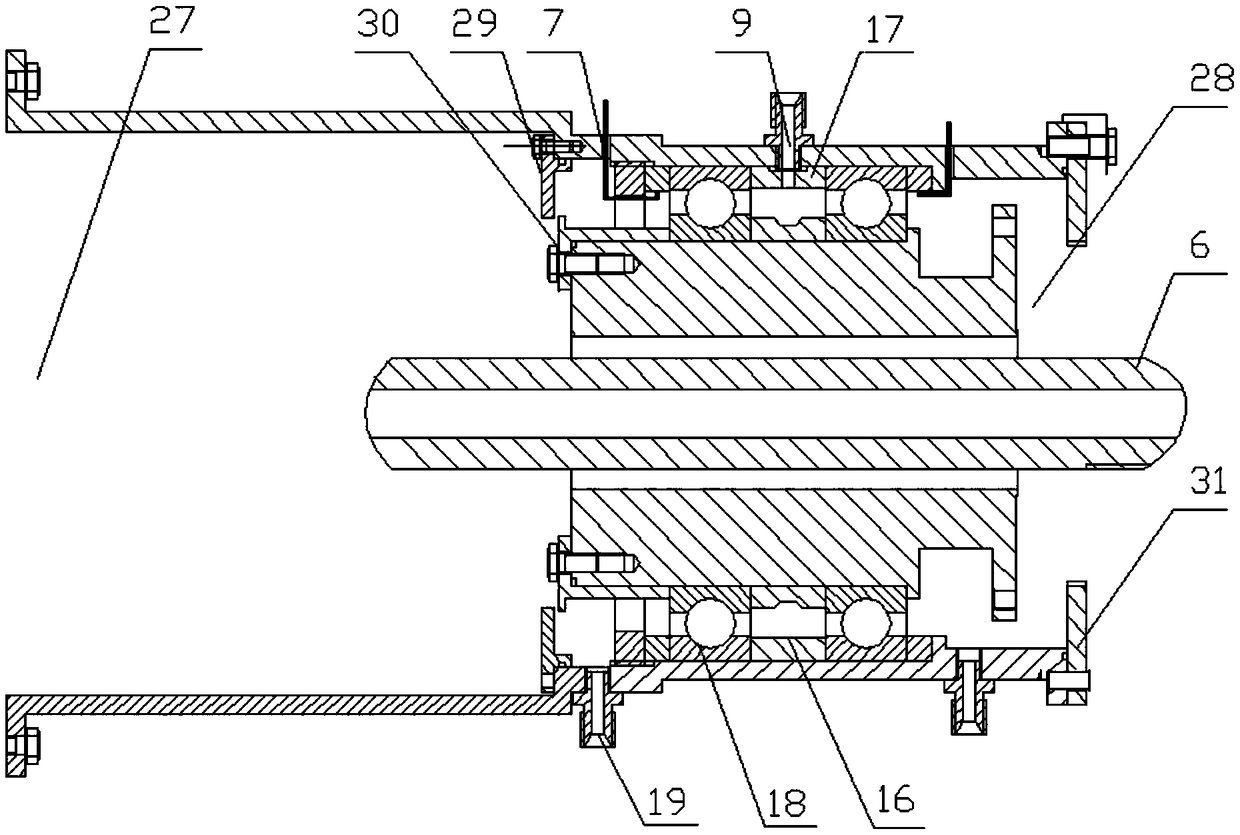
The invention discloses a zero-thrust bearing rotor positioning and axial force testing device and belongs to the field of aeroengine rotor experiments. The zero-thrust bearing rotor positioning and axial force testing device comprises an axial force test soleplate, a shaft coupling, an auto-centering bearing rod, a load dynamometric ring, a reverse dynamometric ring, a test rotor signal line, a multi-degree of freedom tolerance knot, a servo-actuated test shaft, inner and outer locating rings and thrust bearings. The coupling connects a rotor testpiece and the bearing rod. The bearing rod is connected with the multi-degree of freedom tolerance knot and then is connected with an electrical feedthrough. A bearing rod coat is connected with the servo-actuated test shaft. The two thrust bearings on the servo-actuated test shaft are located by the inner and outer locating rings. Axial force on the thrust bearings acts on the load dynamometric ring or the reverse dynamometric ring. The rotor testpiece, the coupling, the auto-centering bearing rod, the servo-actuated test shaft, the inner and outer locating rings, a flange, the load dynamometric ring, the reverse dynamometric ring, the axial force test soleplate and a rotor bearing seat form an auto-balance system. Force of the auto-balance system cannot be transmitted outside, and no rigidity enhancement requirement is required for the base of a rotor system.

Description

technical field [0001] The invention belongs to the technical field of aero-engine rotor experiments, and in particular relates to a positioning and axial force testing device for a non-thrust bearing rotor. Background technique [0002] In the test of aeroengine rotors, sliding bearings are often used for heavy-duty or high-speed rotors, and sliding bearings with thrust function are also used for rotors that generate axial force. For rotors with high axial force, sliding thrust bearings cannot meet the test requirements. For example, in the full temperature and full pressure rotary heat transfer test, the axial force of the rotor can reach 20 tons. For example, the modification of the tester is not only expensive, but also has a narrow application range, low frequency of use, and inconvenient installation. Contents of the invention [0003] Purpose of the present invention: In order to solve the above problems, the present invention proposes a positioning and axial forc...

Claims


Application Information

Patent Timeline
Patent Type & Authority Patents(China)
IPC IPC(8): G01L5/00
CPCG01L5/0009
Inventor 李成刚唐瑞赵博孙坤
Owner AECC SHENYANG ENGINE RES INST
Why Eureka
Try Eureka