a bundler

A binding device and banding technology, which is applied in the direction of binding objects, binding materials, tensioning wires, etc., can solve the problems of bandage wear and bandage breakage, so as to improve the service life, avoid breakage, and reduce bandage scratches The effect of the risk

Active Publication Date: 2018-08-10
ZHEJIANG TOPSUN LOGISTIC CONTROL CO LTD
View PDF7 Cites 0 Cited by
  • Summary
  • Abstract
  • Description
  • Claims
  • Application Information

AI Technical Summary

Problems solved by technology

When the binding device tightens the strap to make the strap tight, because the strap is tighter, the strap wound on the two half-moon shafts will appear slightly relative to the two half-moon shafts every time the ratchet rotates a tooth. In the case of circumferential rotation, the straps wound on the two half-moon shafts will reset again after the straps are loosened; since the arc surface on the half-moon shafts is smooth, the straps located on the innermost ring and the arc surface The circumferential positioning is only achieved by friction force, and the friction force is small. Therefore, the strap located on the innermost ring will rotate slightly relative to the half-moon axis when the strap is tightened, and it will reset after the strap is loosened. During this process, there will be friction between the strap and the half-moon shaft, which will cause wear and tear on the strap. After a long period of use, it will cause the strap to break. The most prone to wear is the arc surface on the half-moon shaft. by a section

Method used


Image

  • a bundler
  • a bundler
  • a bundler

Examples


Embodiment 1

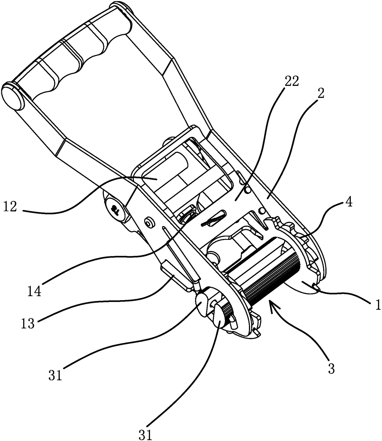
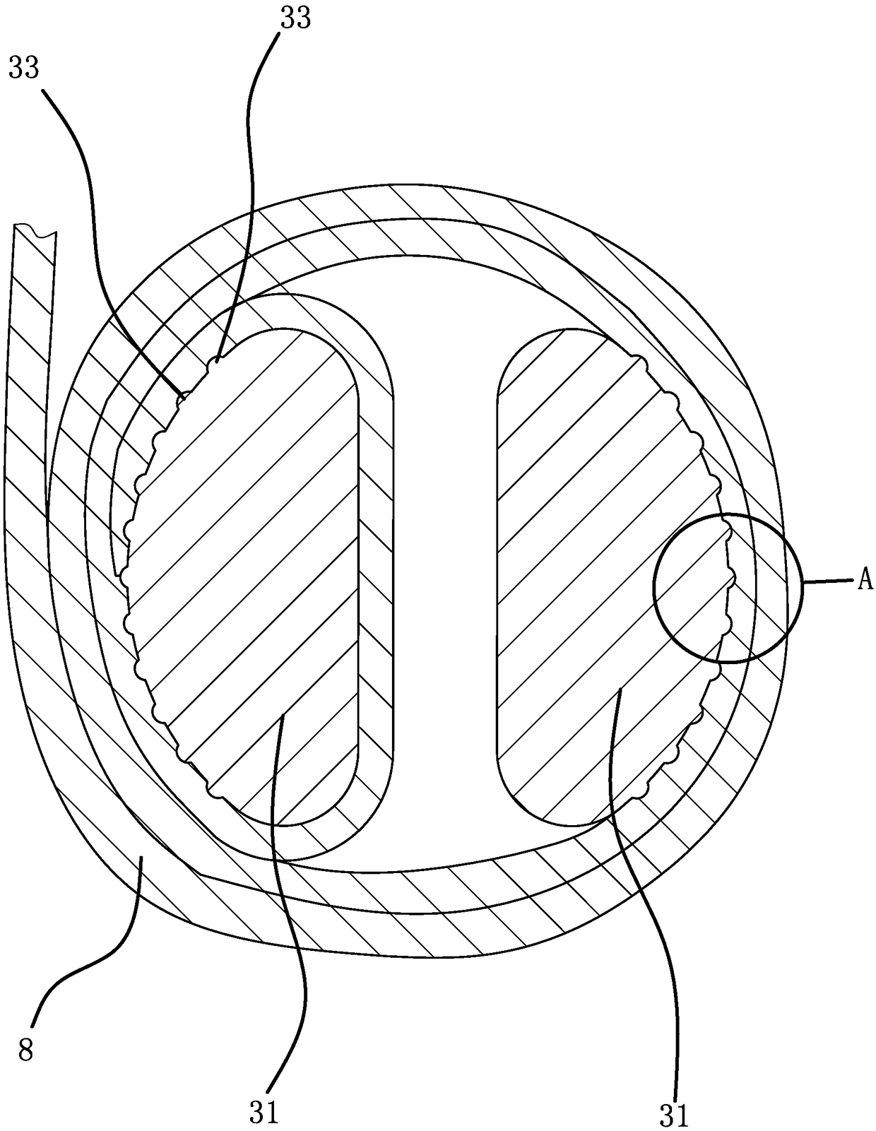
[0033] Such as figure 1 and figure 2 As shown, the binder includes a bracket 1, a handle 2 and a belt shaft 3. The belt shaft 3 includes two half-moon shafts 31, and there is a gap 32 between the two half-moon shafts 31 for the strap 8 to pass through. One end of the bracket 1 and the handle One end of 2 is pivotally connected by belt shaft 3, pivot hole 1 11 is opened on bracket 1, pivot hole 2 21 is opened on handle 2, two half-moon shafts 31 pass through pivot hole 1 1 and pivot hole 2 21 ; One end of the bracket 1 away from the belt shaft 3 is fixed with a fixed shaft 12, the belt shaft 3 is fixed with a ratchet 4, the ratchet 4 is located between the bracket 1 and the handle 2, and the middle part of the ratchet 4 has two half-moon holes, two half-moon holes The shafts 31 pass through the half-moon holes respectively. The handle 2 is provided with a push plate 22 that can be clamped to the ratchet 4 and can drive the ratchet 4 to rotate forward. The push plate 22 can sl...

Embodiment 2

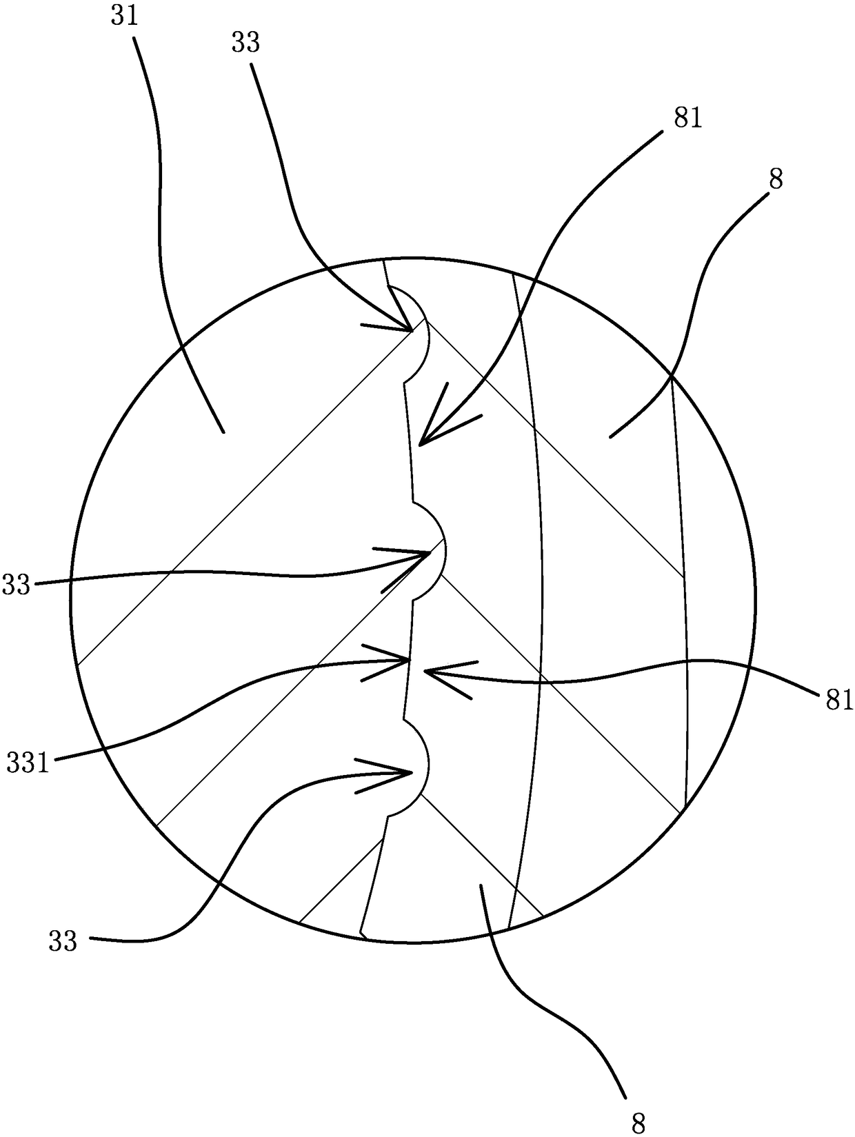
[0037] The structure and principle of this embodiment are basically the same as that of Embodiment 1, the difference is that: Figure 7 As shown, the raised portion 33 includes several oblique ribs one 6 and several oblique ribs two 61, the sides of the oblique rib one 6 and the oblique rib two 61 are arc surfaces, and the adjacent oblique ribs one 6 The distances between them are all the same, the distances between adjacent oblique ribs 2 61 are all the same, and the distance between adjacent oblique ribs 6 is the same as the distance between adjacent oblique ribs 61 , the oblique convex rib one 6 and the oblique convex rib two 61 cross each other to form a network structure, and the adjacent oblique convex rib one 6 and the adjacent oblique convex rib two 61 form a pit 62, and the pit 62 is embedded Section 331. The strap 8 located in the innermost circle is embedded in the pit 62 under the pressure of the outer ring. The shape of the strap 8 embedded in the pit 62 matches ...

Embodiment 3

[0039] The structure and principle of this embodiment are basically the same as that of Embodiment 1, the difference is that: Figure 8 As shown, the raised portion 33 includes several hemispherical bumps 7, the bumps 7 are hemispherical, the bumps 7 are distributed at equal intervals along the length direction of the abutment surface 312, and the plurality of bumps 7 are distributed along the length of the abutment surface 312. The circular arc direction is distributed in an equal arc, and the embedded portion 331 is formed between adjacent bumps 7 . The strap 8 located in the innermost ring is embedded into the embedded part 331 between the convex points 7 under the action of the pressure of the outer ring. The shape of the strap 8 embedded in the embedded part 331 matches the shape of the embedded part 331. The belt 8 will abut against the corresponding convex point 7, and when the two half-moon shafts 31 rotate, the strap 8 embedded in the embedded part 331 will abut again...


PUM


Abstract

The invention provides a binding device, which belongs to the technical field of transportation binding. It solves the technical problems that the existing binding device will cause the binding band to break after being used for a long time. The bundler includes a bracket, a handle and a belt shaft. The bracket and the handle are pivotally connected through the belt shaft. A ratchet is fixed on the belt shaft. There is a stop plate that can prevent the ratchet from reversing. The belt shaft includes two half-moon shafts. There is a gap between the two half-moon shafts for the strap to pass through. The peripheral surfaces of the two half-moon shafts that are relatively far away are arc surfaces. The abutting surface of the abutting surface has a plurality of raised parts, and between the raised parts is an embedded part for the strap to be embedded after deformation. The invention has the advantage of increasing the service life of the strap.

Description

technical field [0001] The invention belongs to the technical field of transportation binding, and relates to a binding device. Background technique [0002] The binding device is a hand-driven tension device, and the binding device realizes the tightening of the binding by winding one end of the binding back. [0003] The structure of the binding device is relatively mature. For example, a hand puller with an improved structure disclosed in the Chinese patent literature [authorized announcement number CN 202368808U] includes a handle, a reel, a ratchet, and a control pull plate. Two ends of the reel pass through the handle. Side plate, two ratchets are sleeved on the left and right sides of the reel, the control pull plate is located between the two side plates of the handle, there is an opening in the middle, and the rear end of the opening is provided with a first trigger piece to control the front end of the pull plate There is a recessed part, and the inner side of the...

Claims


Application Information

Patent Timeline
Patent Type & Authority Patents(China)
IPC IPC(8): B65B13/02B65B13/18
CPCB65B13/025B65B13/18B21F9/00B25B25/00B65B13/22B60P7/083
Inventor 朱正中
Owner ZHEJIANG TOPSUN LOGISTIC CONTROL CO LTD
Why Eureka
Try Eureka