
A mold component for making concrete micro-slit floor and its application

A concrete and floor technology, applied in the direction of mold auxiliary parts, manufacturing tools, ceramic molding machines, etc., can solve the problems affecting the durability of concrete micro-slit floors, accelerate the carbonation process of concrete surface, reduce the effective thickness of steel bar protective layer, etc., and achieve good Anti-sticking, not easy to fall off, and the effect of improving quality

Active Publication Date: 2018-05-29
CHINA AGRI UNIV
View PDF7 Cites 0 Cited by
  • Summary
  • Abstract
  • Description
  • Claims
  • Application Information

AI Technical Summary

Problems solved by technology

[0004] The existence of pockmarks on the concrete surface, on the one hand, reduces the corrosion resistance of the floor, seriously affecting the durability of the concrete micro-slit floor; Improves the surface quality of micro-seamed floors
Therefore, it is necessary to carry out secondary treatment on the surface of the floor with more pockmarks, which consumes labor and materials and increases the construction cost.

Method used


Image

  • A mold component for making concrete micro-slit floor and its application
  • A mold component for making concrete micro-slit floor and its application
  • A mold component for making concrete micro-slit floor and its application

Examples


Embodiment Construction

[0037] Embodiments of the present invention will be further described in detail below in conjunction with the accompanying drawings and examples. The following examples are used to illustrate the present invention, but should not be used to limit the scope of the present invention.

[0038] In the description of the present invention, unless otherwise specified, the meaning of "plurality" is two or more; in addition, the terms "first", "second", "third" and so on are only used for descriptive purposes, It should not be construed as indicating or implying relative importance.

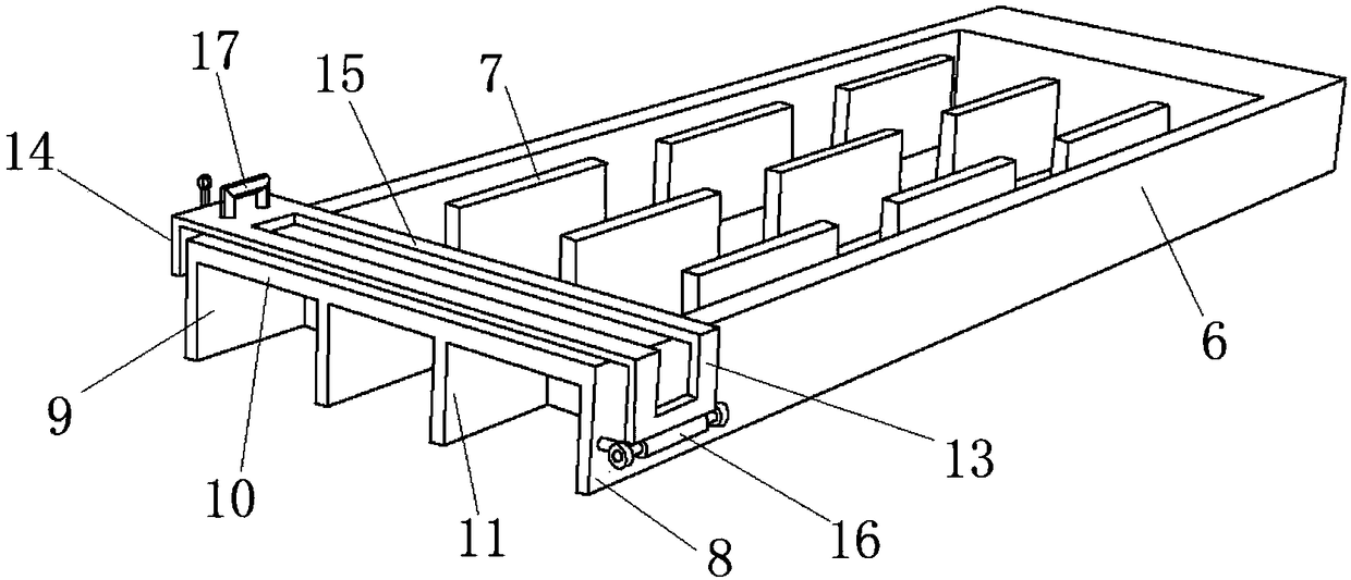
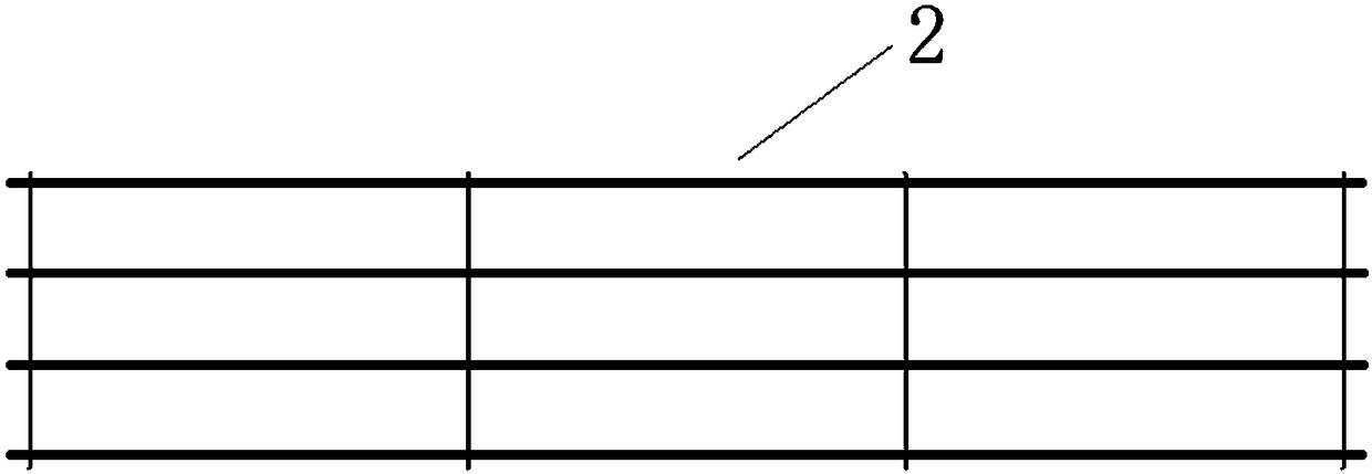
[0039] Such as Figure 1~5 As shown, a mold assembly for making concrete micro-slit floors provided in this embodiment includes a steel mold 1 for pouring concrete into the floor, an isolation layer (not shown in the figure), and 8 A reinforcement mesh 2 welded by root reinforcement, 4 reinforcement positioning cards 3 and a vibrating table 4 positioned below the mold 1.

[0040] The mold 1 includes a...


PUM

PropertyMeasurementUnit
thicknessaaaaaaaaaa
pore sizeaaaaaaaaaa
thicknessaaaaaaaaaa

Abstract

The invention belongs to the technical field of building materials and particularly relates to a mold assembly for manufacturing a concrete narrow-gap slatted floor and application of the mold assembly. The mold assembly comprises a mold and an isolating layer, wherein the mold comprises a base plate and a frame; the frame is formed by assembling four square side plates which are vertically arranged at the periphery of the base plate; a plurality of molding plates are vertically arranged on the base plate; and the isolating layer is attached to the base plate and the side plates. According to the mold assembly disclosed by the invention, the concrete narrow-gap slatted floor is produced by adopting the following method: firstly, uniformly spreading one thin layer of fine sands on the isolating layer, pouring a layer of concrete into the mold assembly and then starting a vibrating table for vibrating; secondly, putting the reinforcing mesh into the mold assembly, and continuously pouring concrete into the mold; when the concrete spills over the reinforcing mesh and is stacked to the top of the mold, plattening the top of the concrete and putting two reinforcing bars into the mold assembly; thirdly, uniformly spreading one layer of carborundum on the surface of the plattened concrete, and immediately turning over and demolding after plattening and forming, thus obtaining a finished product. According to the concrete narrow-gap slatted floor manufactured by adoption of the mold assembly, the pitted surface of the narrow-gap slatted floor surface can be effectively reduced, and surface quality of the floor is improved.

Description

technical field [0001] The invention belongs to the technical field of building materials, and in particular relates to a mold assembly for making concrete micro-slit floors and an application thereof. Background technique [0002] As the name suggests, the micro-slit floor is a floor with gaps. Metal, plastic, concrete, etc. can be used to make a micro-slit floor. Compared with other materials, concrete micro-slit floor has many advantages such as low cost, solid and durable, corrosion resistance, not easy to deform, easy to clean and low thermal conductivity. Therefore, at present, the concrete micro-slit floor has been applied to a certain extent in our country, such as its application in modern pig farms. [0003] However, most of the produced concrete micro-slit floors have many pockmarks on the surface, which affects the appearance of the finished product. During the forming process of the concrete micro-slit floor, due to the material, construction technology and ot...

Claims


Application Information

Patent Timeline
Patent Type & Authority Patents(China)
IPC IPC(8): B28B7/24B28B7/00B28B1/087B28B23/02E04F15/08
CPCB28B1/0873B28B7/0002B28B7/243B28B23/02E04F15/08
Inventor 彭红涛张嘉辉赵祺高继伟顾本家范淋佳郑劭婧
Owner CHINA AGRI UNIV
Learn More