
Preparing method of exhaust way

A technology for exhaust ducts and molds, which is applied to manufacturing tools, ceramic molding machines, etc., can solve problems such as high noise, pockmarked exhaust ducts, and mold deformation, so as to reduce equipment damage, increase service life, and reduce vibration frequency. Effect

Active Publication Date: 2019-05-21
GUANGZHOU CAIDIE ENERGY SAVING TECH
View PDF8 Cites 0 Cited by
  • Summary
  • Abstract
  • Description
  • Claims
  • Application Information

AI Technical Summary

Problems solved by technology

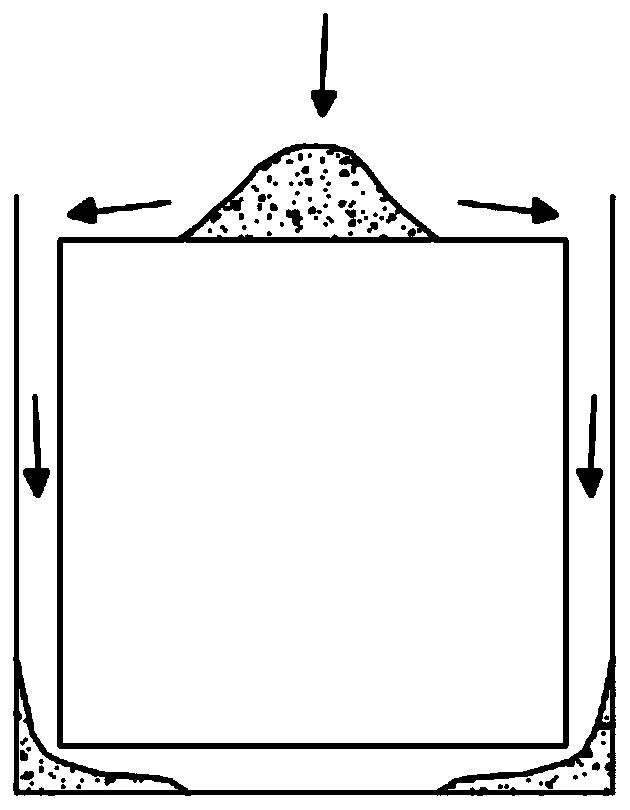
[0008] The molding process of the exhaust channel in the prior art adopts the method of horizontal vibration, which can promote the flow of the slurry on the one hand and discharge the gas in the slurry on the other hand; however, the bottom area of ​​the casting cavity is located below the mold, The gas detached from the slurry will encounter the mold upwards. During the horizontal vibration process, this part of the gas is difficult to flow out to the left or right, and the gas that cannot be discharged is formed on the surface of the exhaust channel, causing the surface of the exhaust channel to Phenomena such as pores and pockmarks appear, and the smoothness is poor
[0009] In the prior art, there is an application of increasing the frequency of horizontal vibration. The main defect of this method is that high-intensity vibration is likely to cause segregation of the grout (concrete segregation), stratification, and uneven internal composition and structure of the grout; Excessive noise in the process can easily lead to deformation of the mold, which is not conducive to the long-term use of the mold;
[0010] In order to reduce the occurrence of pockmarks and other phenomena, there is also the application of increasing the water-cement ratio of the slurry to increase the fluidity of the slurry in the prior art. Since the overall thickness of the exhaust channel is relatively thin, generally about 15mm, the water-cement ratio of the slurry is improved. After the gray ratio, the strength of the exhaust duct will be insufficient, and it is difficult to meet the requirements of the vertical bearing capacity of the exhaust duct products specified in the industry standard; moreover, after increasing the water-cement ratio of the slurry, there are still obvious numbness. surface phenomenon

Method used


Image

  • Preparing method of exhaust way
  • Preparing method of exhaust way
  • Preparing method of exhaust way

Examples


Embodiment 1

[0070] Embodiment 1 (tilted vibration mode one)

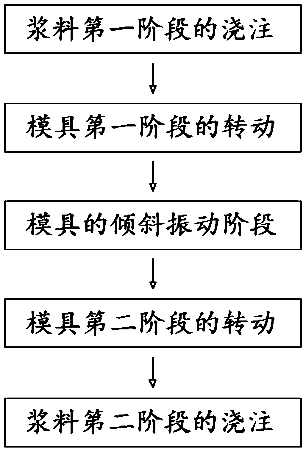
[0071] Such as figure 1 As shown in -8, a method for preparing an exhaust duct, after the mold is positioned, the following process is performed:

[0072] Pouring of the first stage of slurry:

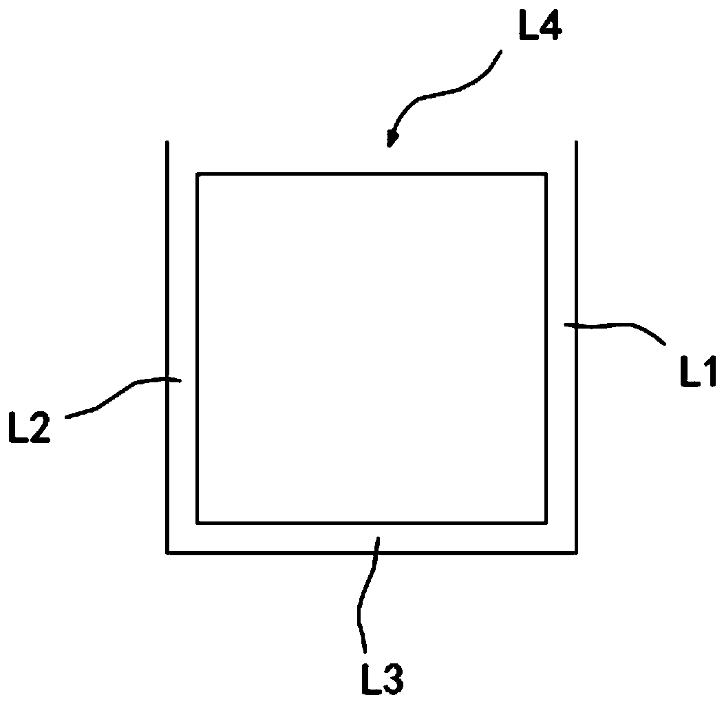
[0073] The slurry is poured in the top area L4 of the mold, the fluid slurry flows into the first side area L1 and the second side area L2, and gathers in the bottom area L3, and the slurry is continuously poured until the slurry is filled to the bottom Area L3;

[0074] Preferably, during the pouring process of the slurry in the first stage, the amount of slurry dispersed into the first side area L1 and the second side area L2 is generally the same or close, and after the slurry fills the bottom area L3, the first There is still a certain amount of slurry in the side area L1 and the second side area L2.

[0075] Wherein, during the pouring process of the slurry in the first stage, the horizontal vibration of the mold may or may n...

Embodiment 2

[0095] Embodiment 2 (tilted vibration mode two)

[0096] Such as Figure 9 -16. A method for preparing an exhaust channel, especially a method for preparing a mechanism exhaust channel. After the mold is positioned, the following process is performed:

[0097] Rotation of the first stage of the mold:

[0098] Rotate the mold around the first direction toward the first side area L5 to an inclined posture, at this time, an inclination β is formed between the bottom area L7 in the casting cavity and the horizontal plane;

[0099] Preferably, the inclination angle β formed between the bottom area L7 in the casting cavity and the horizontal plane is 10°-45°, further, the inclination angle β is about 20°, and the inclination angle β in this embodiment is 15°, Compared with the oblique vibration mode in Embodiment 1, the inclination angle in this embodiment is smaller, and the vibration effect is more prominent.

[0100] Wherein, after the mold rotates to an inclined posture, th...

Embodiment 3

[0121] Embodiment 3 (tilted vibration mode two)

[0122] A method for preparing an exhaust duct. The difference between this embodiment and Embodiment 2 is that: in the tilting vibration stage of the mold, there are also:

[0123] Periodic swinging process of the mold: the mold alternately rotates around the first direction toward or away from the first side area to change the inclination angle formed between the plane of the bottom area in the casting cavity and the horizontal plane, through multiple cycles During the swing process, the gas in the bottom area (including the gas mixed in the slurry in the bottom area) can be completely exhausted, and the air holes and pockmarks on the side wall of the exhaust channel (especially the side wall formed in the bottom area of ​​the casting cavity) can be avoided. .


PUM


Abstract

The invention provides a preparing method of an exhaust way. A casting forming cavity matched with the exhaust way in shape is formed in a mold, the casting forming cavity is provided with a top areaand a bottom area which are arranged vertically, a first side area and a second side area, the first side area and the second side area are symmetrically arranged on the two sides of the bottom area,in the casting process of slurry, a mold rotates to be in the inclined posture in a manner of surrounding the first direction in an at least partial staged manner, an inclined angle is formed betweenthe plane where the bottom area in the casting forming cavity and the horizontal plane, the mold is in the inclined posture, mold vibration is carried out in a continuous or staged manner. Vibration is carried out under the mold inclined posture, gas in slurry can be sufficiently discharged, and pitted surfaces, gas holes and the like generated on the exhaust way can be reduced.

Description

technical field [0001] The invention belongs to the technical field of residential exhaust ducts, and in particular relates to a method of making the mold in a tilted state and vibrating the mold at some stages in the preparation process of the exhaust duct, so as to fully discharge the gas in the slurry to reduce the exhaust duct. A method for preparing an exhaust duct that produces pockmarks, pores, and the like. Background technique [0002] Exhaust duct is a building component widely used in residential buildings to remove oily fumes in the kitchen and exhaust gas in the bathroom. The exhaust duct is prefabricated and assembled to the designated location in the building after being transported to the construction site. [0003] The current exhaust ducts are mostly made by hand, which has the disadvantages of occupying a large space, requiring high technical proficiency for operators, and difficult to control the thickness uniformity of the side walls of the exhaust ducts...

Claims


Application Information

Patent Timeline
Patent Type & Authority Applications(China)
IPC IPC(8): B28B1/08
Inventor 李志李惠红聂法玉谭源生
Owner GUANGZHOU CAIDIE ENERGY SAVING TECH
Learn More