
Vibrating residue removal mechanism of split connecting rod bolt assembling facility

A technology for assembling equipment and cracking connecting rods, which is applied in the direction of cleaning methods and tools, chemical instruments and methods, etc., can solve problems affecting assembly accuracy and quality, and unclean slag removal, so as to improve assembly accuracy and quality, easy cleaning, Improves the effect of reset engagement

Inactive Publication Date: 2016-12-07
JILIN UNIV +1
View PDF5 Cites 3 Cited by
  • Summary
  • Abstract
  • Description
  • Claims
  • Application Information

AI Technical Summary

Problems solved by technology

[0004] Aiming at the technical problem that the slag removal on the fracture surface in the cracking connecting rod bolt assembly is not clean and affects the assembly accuracy and quality, the present invention provides a vibration and slag removal mechanism for the cracking connecting rod bolt assembly equipment. The technical scheme is as follows:

Method used


Image

  • Vibrating residue removal mechanism of split connecting rod bolt assembling facility
  • Vibrating residue removal mechanism of split connecting rod bolt assembling facility
  • Vibrating residue removal mechanism of split connecting rod bolt assembling facility

Examples


specific Embodiment approach

[0031] In order to further illustrate the technical solution of the present invention, in conjunction with the accompanying drawings, the specific implementation of the present invention is as follows:

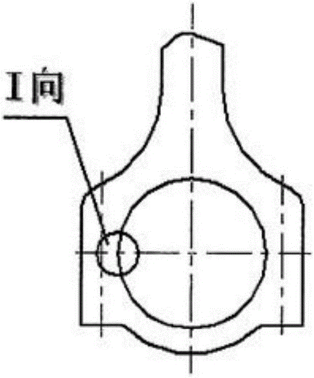
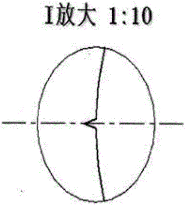
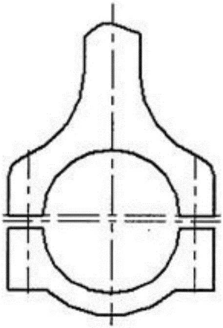
[0032] Such as Figures 1a-1d As shown, the connecting rod cracking process includes: a. pre-processing two cracking grooves in the big end hole of the connecting rod; b. breaking and dissecting the connecting rod; c. resetting and engaging the connecting rod cover and the connecting rod body. The present invention is aimed at the vibration slag removal link before the connecting rod cover and the connecting rod body are reset and engaged.

[0033] Such as Figure 2a-2c As shown, the present invention provides a vibratory slag removal mechanism for cracking connecting rod bolt assembly equipment. In order to more clearly illustrate the technical solution of the present invention, the following briefly describes other key components in the cracking connecting rod bolt assembly...


PUM


Abstract

The vibration and slag removal mechanism of the cracking connecting rod bolt assembly equipment is composed of the cover end vibration cylinder, the cover end vibration block, the rod end vibration cylinder, the rod end vibration block, the slider, the rod / cover separation cylinder, the connecting plate, and the positioning of the big head hole of the connecting rod The moving block and the connecting rod big end hole positioning fixed block are composed; the connecting rod big end hole positioning moving block is fixedly installed on the slider body, the rod end vibration cylinder is fixedly installed on the lower side of the upper panel of the frame, and the rod / cover is separated from the oil cylinder. Installed under the upper panel of the frame; the cover end vibration block is fixedly installed on the piston rod of the cover end vibration cylinder, and the rod end vibration block is fixedly installed on the piston rod of the rod end vibration cylinder; one end of the connecting plate is connected with the slider body It is fixedly connected, and the other end is fixedly connected with the piston rod of the rod / cover separation cylinder; the side of the positioning block of the big head hole of the connecting rod is provided with a high-pressure air hole. The invention effectively removes residues on the fractured surface of the big head hole of the connecting rod, greatly improves the reset meshing condition between the cover end of the cracked connecting rod and the rod body, and improves the assembly precision and quality of the bolts.

Description

technical field [0001] The invention belongs to the technical field of engine connecting rod cracking processing, and in particular relates to a vibration and slag removal mechanism of cracking connecting rod bolt assembly equipment. Background technique [0002] Connecting rod cracking processing is the latest technology in the manufacture of engine connecting rods. The technical principle of the new process of connecting rod cracking processing is to first process two cracking grooves on both sides of the center of the semi-finishing connecting rod big hole, then perform directional cracking on the special equipment for cracking, and finally assemble the bolts at a fixed torque on the special bolt assembly machine. The new technology of connecting rod cracking processing adopts the fracture separation method to divide the connecting rod body and connecting rod cover, and uses the canine staggered fracture coupling surface to realize the precise meshing and positioning of t...

Claims


Application Information

Patent Timeline
IPC IPC(8): B08B7/02
CPCB08B7/02
Inventor 杨慎华寇淑清邓春萍赵勇林宝君杨磊
Owner JILIN UNIV
Learn More