
Plate filter press

A plate-type filter press, plate-frame technology, applied in the direction of filtration separation, separation methods, chemical instruments and methods, etc., can solve the problems of high labor intensity and low efficiency, achieve improved work efficiency, wide application range, and reduce manual labor intensity effect

Inactive Publication Date: 2018-10-26
幸南(丹阳)涂装工业有限公司
View PDF3 Cites 1 Cited by
  • Summary
  • Abstract
  • Description
  • Claims
  • Application Information

AI Technical Summary

Problems solved by technology

[0003] However, in the existing plate filter press, when the filter cake is cleared out after filtering, it is first necessary to loosen the pressing device, then manually separate the plate frame, and then clear the filter cake, which is not only labor-intensive, but also low in efficiency.
[0004] A patented plate filter press with buffer function, the application number is CN201520646910.7, which discloses a plate filter press, including a frame and a filter plate and a filter frame arranged on the frame, the filter plate and filter Frames are stacked alternately to form a group of filter units. Filter cloths are set on both sides of the filter plate. The frame is also equipped with a concentrated liquid inlet pipe, a clear night liquid outlet pipe and a concentrated liquid delivery pump. The concentrated liquid One end of the liquid inlet pipe communicates with the thick liquid delivery pump, and the other end communicates with the inner space of the filter frame. The clear liquid outlet pipe is the same as the inner space of the filter plate. device, the concentrated liquid inlet pipe communicates with the interior of the filter frame through a flexible joint I, and the clear liquid outlet pipe communicates with the inside of the filter plate through a flexible joint II; A buffer is also provided, and the buffer includes a barrel, and a spiral baffle is arranged inside the barrel; although this patent has high filtration accuracy, it still requires personnel to manually disassemble the filter unit and discharge the slag

Method used


Image

  • Plate filter press
  • Plate filter press
  • Plate filter press

Examples


Embodiment Construction

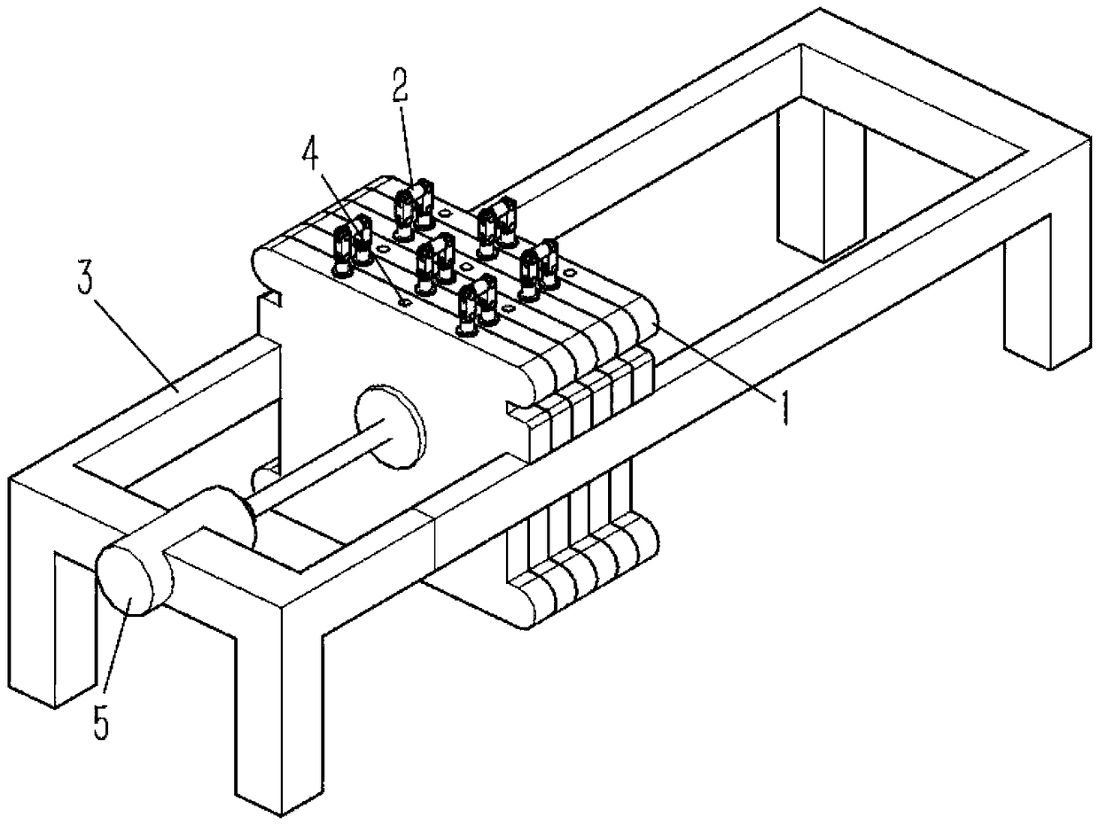
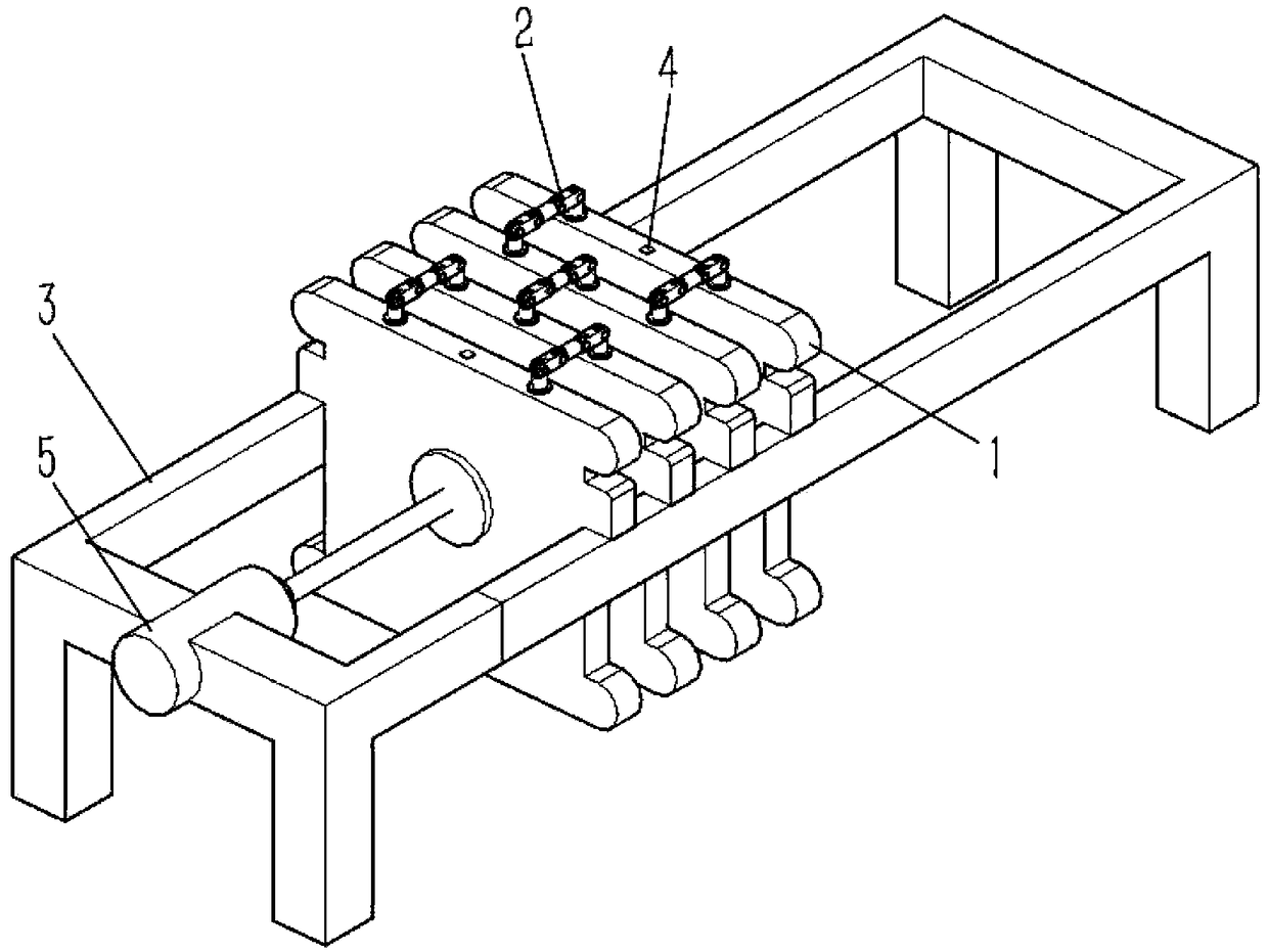
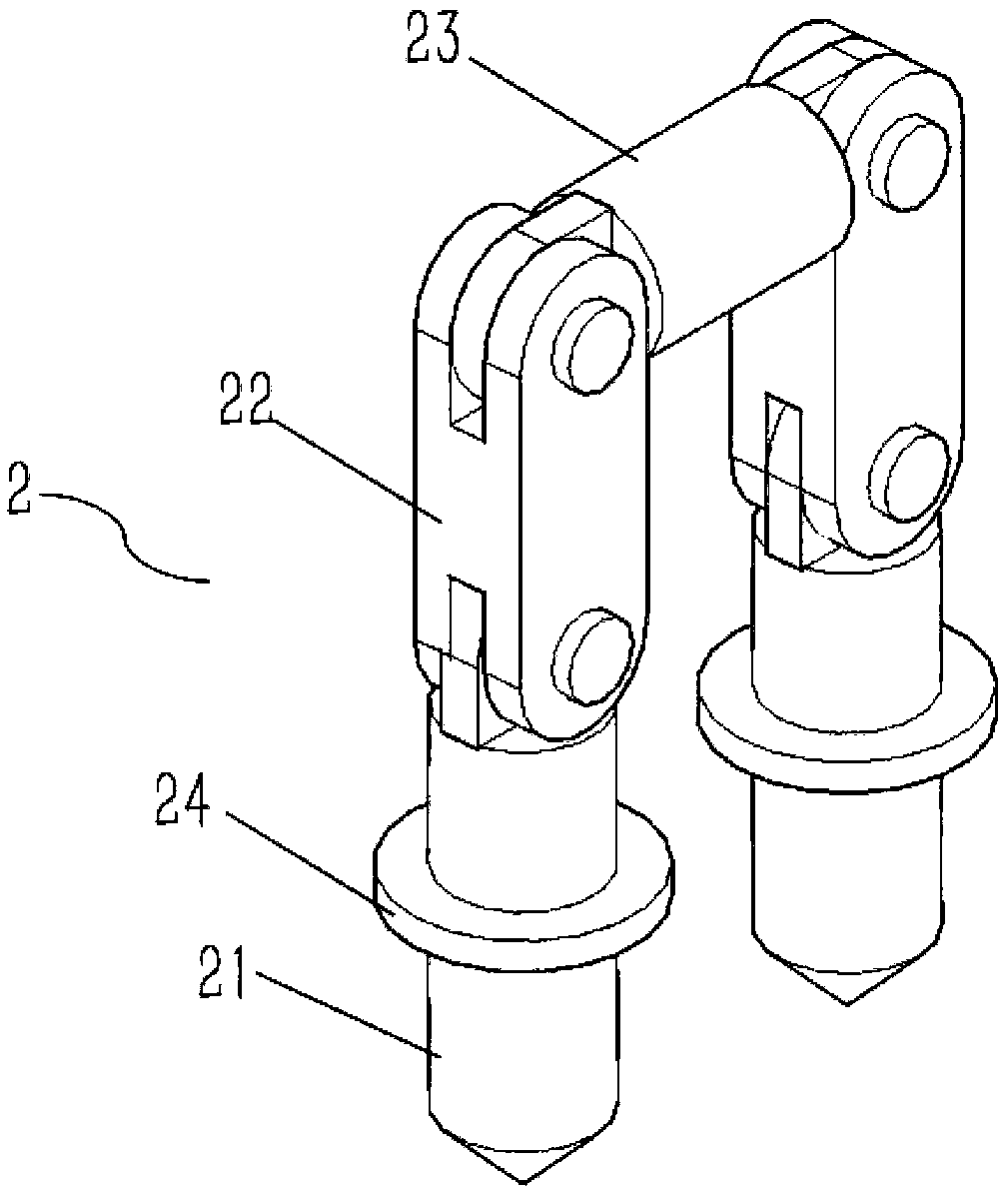
[0022] Such as Figure 1 to Figure 4 As shown, a plate filter press includes several plate frames 1 stacked in sequence along the horizontal direction, with protrusions on both sides of the plate frame 1, and guide rails 3 on the lower side of the protrusions of the plate frame 1, And the plate frame 1 can reciprocally slide on the guide rail 2; the center of the end of the guide rail 3 is provided with a hydraulic cylinder 5, and the telescopic direction of the hydraulic cylinder 5 is perpendicular to the surface of the plate frame 1; The upper side of the plate frame 1 is provided with a groove 4, and also includes a linkage device 2, and the linkage device 2 includes a positioning pin 21 and a linkage rod 23 arranged parallel to the vertical direction, and the upper end of the positioning pin 21 is provided with A rotating rod 22 is arranged, the lower end of the rotating rod 22 is hinged with the upper end of the positioning pin 21 , and the two ends of the linkage rod 23 ...


PUM


Abstract

The invention provides a plate filter press and relates to the field of plate filter presses. The plate filter press comprises a plurality plate frames which is stacked along the horizontal directionin sequence, lugs are arranged on two sides of the plate frames, a straightness guiding rail is arranged on lower sides of the lug, and the plate frames can slide on the straightness guiding rail reciprocatingly; a hydraulic cylinder is arranged in the middle of one end of the straightness guiding rail, and the expansion direction of the hydraulic cylinder is perpendicular to the surfaces of the plate frames; grooves are arranged in upper sides of the plate frames; the plate filter press further comprises a linkage device which comprises positioning pins and linkage rods which are parallelly arranged along the vertical direction, a rotating rod is arranged at the upper end of each positioning pin, the lower end of the rotating rod is hinged with the upper end of each positioning pin, and two ends of the linkage rods are respectively hinged with upper ends of the rotating rods; the bottom of one positioning pin is inserted in one groove of each plate frame, and the bottom of the other positioning pin is inserted in the groove o the other neighboring plate frame. By the arrangement, filter residues are removed conveniently, labor intensity can be lowered, and working efficiency is improved.

Description

technical field [0001] The invention belongs to the field of plate filter presses, in particular to a plate filter press. Background technique [0002] Plate filter press is also plate and frame filter press, plate and frame filter press. The plate filter press has a large filtration area, a large flow rate, and a wide range of applications, so it is widely used in chemical and other industries. The plate filter press is made up of plates and frames arranged alternately. The two sides of the filter plate are covered with filter cloth, and the plate and frame are compressed with a pressing device, that is, a filter press chamber is formed between the plate and the frame. There is a small hole in the same part of the upper end of the plate and the frame. After being compressed, it becomes a channel. The sludge pressurized to 0.2-0.4MPa enters the filter chamber through this channel. The surface of the filter plate is engraved with grooves. There are holes for the filtrate to...

Claims


Application Information

Patent Timeline
IPC IPC(8): B01D25/12B01D25/172
CPCB01D25/12B01D25/172
Inventor 吕杰
Owner 幸南(丹阳)涂装工业有限公司
Learn More