


Quick Research
Generate reliable direction feasibility study reports for your R&D in just a few steps.

Technical Q&A
Discover and master advanced knowledge NOW. Basics, ideas, possibilities, all at once.

Find Solutions
As an expert in R&D theories, this can generate solutions to your technical problems instantly.

Evaluate Feasibility
Analyze your overall solution with one click, know your potential R&D risks in advance.

Monitor Landscape
Get weekly tech updates, stay abreast of the latest tech innovations and key insights.
Medical automatic cleaning machine
A technology of automatic cleaning machine and outer casing, which is applied in the direction of cleaning method using liquid, using re-radiation, cleaning method and utensils, etc., which can solve the problems of different shapes and sizes of medical equipment and low efficiency.
- Summary
- Abstract
- Description
- Claims
- Application Information
AI Technical Summary
Problems solved by technology
Method used
Image

Examples
Embodiment 1
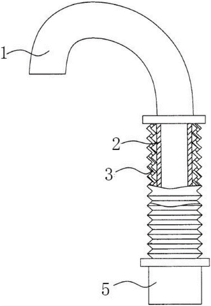
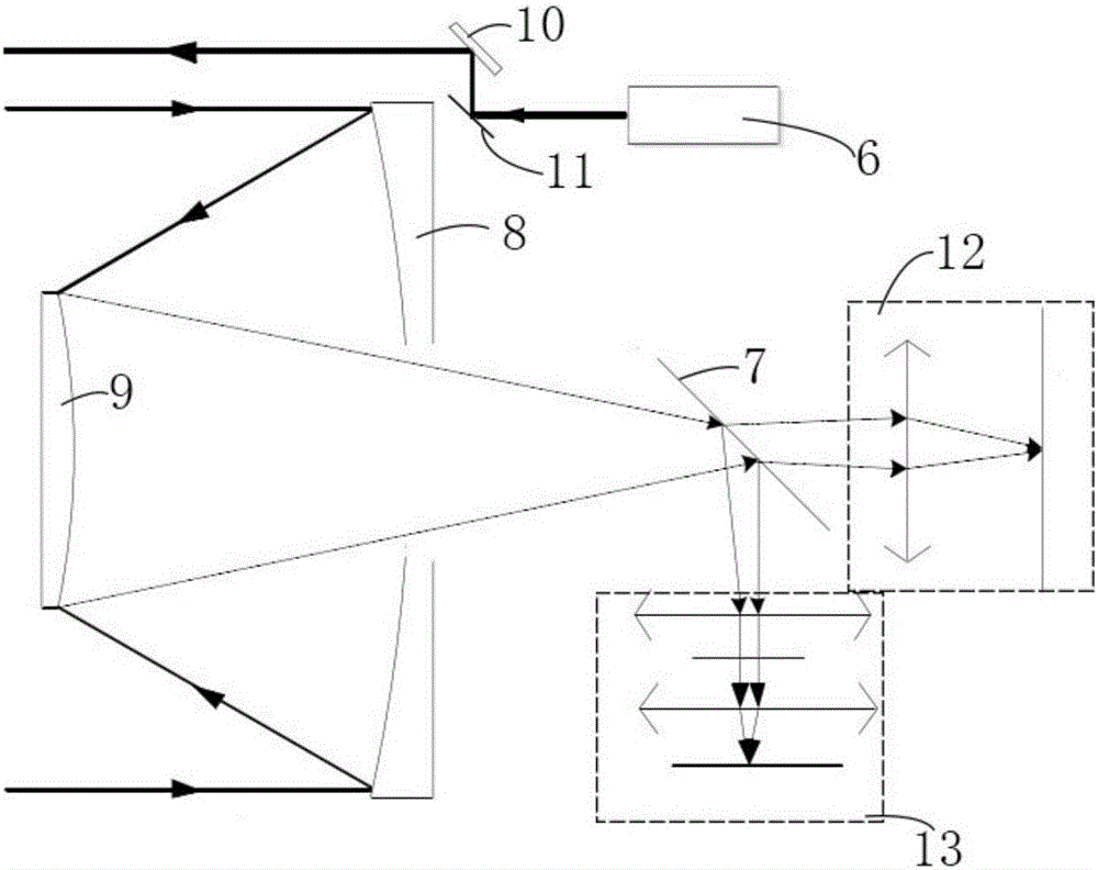
[0038] The device of the present invention comprises a water gun body 1, a total water gun base 5 and a plurality of detachable sub-water gun bases, such as figure 1 As shown, the water gun body 1 is detachably arranged on the main water gun base 5, and the sub-water gun bases are installed at different positions around the washbasin, which is convenient for users to use. One end of the water gun body 1 is a water outlet, and the other end is a water inlet. The water inlet is connected with a water inlet pipe 2 and a flexible pipe 3 wrapping the water inlet pipe 2. The water inlet pipe 2 and the flexible pipe 3 extend to the inside of the main water gun base 5 and are connected with a solenoid valve. The solenoid valve controls The connection of the water inlet pipe 2. One side of the total water gun base 5 is provided with a sensing device, and the sensing device includes an optical receiving component, an infrared emitting component 22 , a distance measuring component 13 an...
Embodiment 2
[0075] The device of the present invention comprises a water gun body 1, a total water gun base 5 and a plurality of detachable sub-water gun bases, such as figure 1 As shown, the water gun body 1 is detachably arranged on the main water gun base 5, and the sub-water gun bases are installed at different positions around the washbasin, which is convenient for users to use. One end of the water gun body 1 is a water outlet, and the other end is a water inlet. The water inlet is connected with a water inlet pipe 2 and a flexible pipe 3 wrapping the water inlet pipe 2. The water inlet pipe 2 and the flexible pipe 3 extend to the inside of the main water gun base 5 and are connected with a solenoid valve. The solenoid valve controls The connection of the water inlet pipe 2. One side of the total water gun base 5 is provided with a sensing device, and the sensing device includes an optical receiving component, an infrared emitting component 22 , a distance measuring component 13 an...
Embodiment 3
[0112] The device of the present invention comprises a water gun body 1, a total water gun base 5 and a plurality of detachable sub-water gun bases, such as figure 1 As shown, the water gun body 1 is detachably arranged on the main water gun base 5, and the sub-water gun bases are installed at different positions around the washbasin, which is convenient for users to use. One end of the water gun body 1 is a water outlet, and the other end is a water inlet. The water inlet is connected with a water inlet pipe 2 and a flexible pipe 3 wrapping the water inlet pipe 2. The water inlet pipe 2 and the flexible pipe 3 extend to the inside of the main water gun base 5 and are connected with a solenoid valve. The solenoid valve controls The connection of the water inlet pipe 2. One side of the total water gun base 5 is provided with a sensing device, and the sensing device includes an optical receiving component, an infrared emitting component 22 , a distance measuring component 13 an...
PUM
| Property | Measurement | Unit |
|---|---|---|
| Center distance | aaaaa | aaaaa |
| Diameter | aaaaa | aaaaa |
| Arc radius | aaaaa | aaaaa |
Abstract
Description
Claims
Application Information
 - R&D Engineer
- R&D Manager
- IP Professional
- Industry Leading Data Capabilities
- Powerful AI technology
- Patent DNA Extraction
Browse by: Latest US Patents, China's latest patents, Technical Efficacy Thesaurus, Application Domain, Technology Topic, Popular Technical Reports.
© 2024 PatSnap. All rights reserved.Legal|Privacy policy|Modern Slavery Act Transparency Statement|Sitemap|About US| Contact US: help@patsnap.com