
Oil pan machining device

An oil pan and machining technology, applied in the field of machining devices, can solve problems such as clamping deformation and insufficient clamping rigidity of oil pan parts, and achieve the effects of ensuring machining accuracy, improving production efficiency, and realizing automation

Inactive Publication Date: 2016-11-30
苏州金澄精密铸造有限公司
View PDF6 Cites 1 Cited by
  • Summary
  • Abstract
  • Description
  • Claims
  • Application Information

AI Technical Summary

Problems solved by technology

[0004] The technical problem to be solved by the present invention is to provide a machining device for the oil pan to solve the problem of insufficient rigidity of the machining and clamping of the oil pan in the current machining process of the oil pan and that the parts of the oil pan are installed in the clamping process. clip deformation problem

Method used


Image

  • Oil pan machining device
  • Oil pan machining device
  • Oil pan machining device

Examples


Embodiment Construction

[0023] Below in conjunction with accompanying drawing and embodiment the present invention is further described

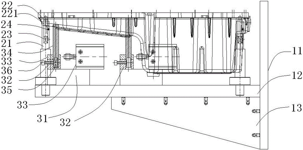
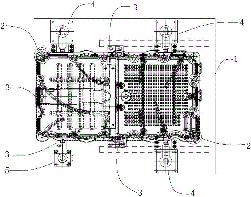
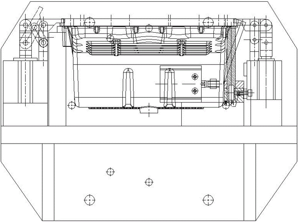
[0024] like Figure 1 to Figure 7 As shown, a machining device for an oil pan includes a bracket assembly 1, a number of positioning pin assemblies 2, a number of support column assemblies 3, a number of support blocks 4 and a number of pressure plate assemblies 5, and the bracket assembly 1 is used for reliable installation of the device in machining Inside the equipment, the bracket component 1 is threadedly connected with the processing equipment. The positioning pin component 2 is located at the upper end of the bracket component 1 and corresponds to the positioning hole of the oil pan. The positioning pin component 2 and the support column component 3 are both floating design. Both the block 4 and the pressure plate assembly 5 are located at the upper end of the bracket assembly 1 and distributed around the oil pan, and the pressure plate assembly 5 is located...


PUM


Abstract

The invention discloses a machining device for an oil pan, comprising a bracket assembly, a number of positioning pin assemblies, a number of support column assemblies, a number of support blocks and a number of pressure plate assemblies, the bracket assembly is used for The fixture is reliably installed in the processing equipment, the positioning pin assembly is located at the upper end of the bracket assembly, the positioning pin assembly and the support column assembly are all provided with floating devices, and the support column assembly, support block and pressing plate assembly are all located at the upper end of the bracket assembly and Distributed around the oil pan, the beneficial effect of this oil pan processing device is to achieve sufficient rigidity for the clamping of the oil pan parts during processing, effectively preventing the deformation of the oil pan parts by the clamping and the damage to the oil pan parts. The impact of machining accuracy improves the yield rate of parts processing. In addition, the clamping force is constant and fast, the efficiency is high, and the work intensity of workers is reduced.

Description

technical field [0001] The invention relates to a machining device, in particular to a machining device for an oil pan. Background technique [0002] The oil pan is located at the lower part of the engine and can be disassembled and sealed by the axle box as an oil storage tank. The oil pan is the lower half of the crankcase, also known as the lower crankcase, and its function is to close the crankcase as an oil storage tank. The outer casing prevents impurities from entering, and collects and stores the lubricating oil flowing back from the friction surfaces of the diesel engine, dissipates part of the heat, and prevents the oxidation of the lubricating oil. The oil pan is mostly stamped from thin steel plates, and the shape is more complicated. , It is equipped with an oil stabilizing baffle inside to avoid the shock and splash on the right side caused by the diesel engine bumping, which is conducive to the precipitation of lubricating oil impurities, and an oil dipstick i...

Claims


Application Information

Patent Timeline
Patent Type & Authority Applications(China)
IPC IPC(8): B23Q3/00
CPCB23Q3/00B23Q2703/10
Inventor 贺鹏志
Owner 苏州金澄精密铸造有限公司
Learn More