Temperature sensor for interior of oil immersed transformer and manufacturing method of temperature sensor

A technology of temperature sensor and oil-immersed transformer, applied in the direction of thermometers, thermometers, thermometer parts, etc. with physical/chemical changes, can solve the problems of installation and use damage, low reliability, drift, etc., to achieve convenient monitoring, reliable High performance and simple structure

Active Publication Date: 2016-11-23
深圳阿珂法先进科技有限公司
View PDF7 Cites 5 Cited by
  • Summary
  • Abstract
  • Description
  • Claims
  • Application Information

AI Technical Summary

Problems solved by technology

[0003] Traditional temperature sensors cannot meet the requirements of being placed inside windings or iron cores. Existing fiber optic temperature sensors often have the following problems:
[0004] (1) The packaging structure of the optical fiber temperature sensor used to measure the internal temperature of the oil-immersed transformer is complex and the reliability is low;
[0005] (2) Due to the desensitization effect of the existing fiber grating-based temperature sensor, there are problems such as drift and poor precision in long-term work;
[0006] (3) The structural design of the existing optical fiber temperature sensor is not compatible with the transformer manufacturing process, it is easy to be damaged during installation and use, and its reliability is low

Method used


Image

  • Temperature sensor for interior of oil immersed transformer and manufacturing method of temperature sensor
  • Temperature sensor for interior of oil immersed transformer and manufacturing method of temperature sensor
  • Temperature sensor for interior of oil immersed transformer and manufacturing method of temperature sensor

Examples


Embodiment 1

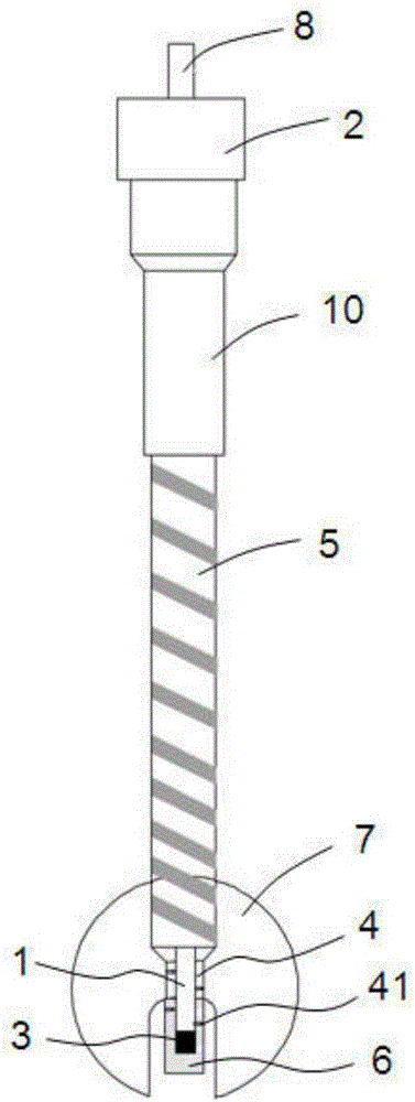
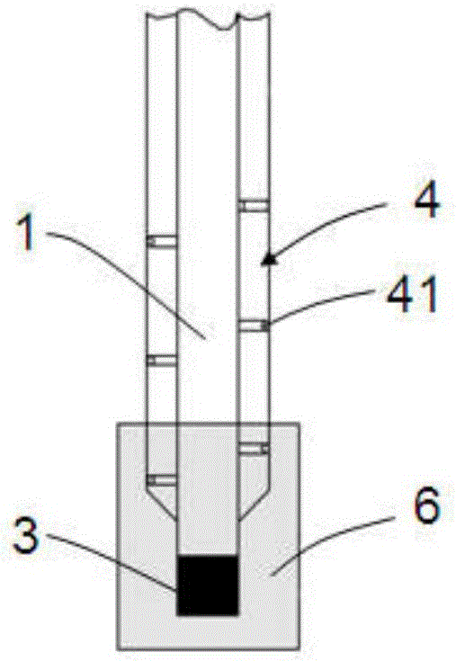
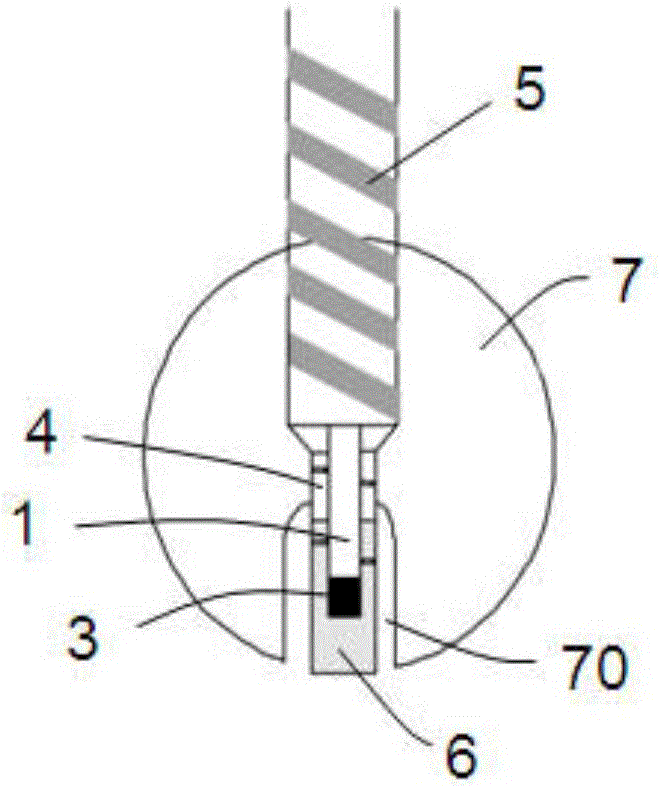
[0031] refer to figure 1 , the temperature sensor for the interior of the oil-immersed transformer according to the embodiment of the present invention includes an optical fiber 1, an optical fiber connector 2 arranged at the first end of the optical fiber 1, a heat-sensitive element 3 packaged at the second end of the optical fiber 1, and a first protective sheath 4 And the second protective sleeve 5, the first protective sleeve 4 is sleeved on the outer peripheral surface of the second end of the optical fiber 1, the second protective sleeve 5 is sleeved on the other outer peripheral surface of the optical fiber 1, and the first protective sleeve 4 is provided with a radial direction through a plurality of through holes 41 . The optical fiber connector 2 can be any one of metal optical fiber connectors such as ST, FC, and SMA, which is convenient for connecting with other devices.

[0032] combine figure 2 As shown, the end of the first protective sheath 4 , the second en...

Embodiment 2

[0053] Such as Figure 6 As shown, different from the embodiment, the size of the fixed disk 7 of the present embodiment is smaller, the first protective cover 4 is fixed on the fixed disk 7, and the length is greater than that of the fixed disk 7, and its end protrudes from the fixed disk 7 In addition, this design can be applied to detection in a narrower space.


PUM


Abstract

The invention discloses a temperature sensor for the interior of an oil immersed transformer. The temperature sensor comprises an optical fiber, an optical fiber connector arranged at the first end of the optical fiber, a thermosensitive element packaged at the second end of the optical fiber, a first protective sleeve and a second protective sleeve. The outer periphery of the second end of the optical fiber is sleeved with the first protective sleeve, the other outer peripheries of the optical fiber are sleeved with the second protective sleeve, and the first protective sleeve is provided with multiple through holes which are through in the radial direction. The invention further discloses a manufacturing method of the temperature sensor for the interior of the oil immersed transformer. The temperature sensor is small in size, simple in structure and high in reliability, structural damage, precision reduction and other situations are avoided, the requirements that the temperature sensor is embedded into a winding or an iron core can be well met, and the temperature of the interior of the oil immersed transformer is convenient to monitor.

Description

technical field [0001] The invention relates to the technical field of power transformation equipment, in particular to a temperature sensor used in an oil-immersed transformer and a manufacturing method thereof. Background technique [0002] Transformer is one of the important equipment in the power system, and it is of great significance to ensure its safe operation. Insulation aging is the root cause of transformer life shortening, and high temperature will accelerate winding insulation aging. In order to ensure safe and reliable operation of the transformer and prolong the service life of the transformer, it is very important to monitor the hot spot temperature, core temperature and oil temperature of the transformer winding. [0003] Traditional temperature sensors cannot meet the requirements of being placed inside windings or iron cores. Existing fiber optic temperature sensors often have the following problems: [0004] (1) The packaging structure of the optical fib...

Claims


Application Information

Patent Timeline
IPC IPC(8): G01K11/32G01K1/08G01K1/14
CPCG01K1/08G01K1/14G01K11/32
Inventor 董玉明岳孟果焦国华吕建成鲁远甫罗阿郁
Owner 深圳阿珂法先进科技有限公司
Why Eureka
Try Eureka