
Hydraulic machine for fine blanking of sheet metal

A technology of precision blanking and hydraulic press, applied in the field of forging machinery, can solve the problem that blanking parts cannot meet the requirements of surface finish or dimensional accuracy, cannot meet the requirements of high-precision fine punching die, and the clamping force of upper push cylinder and lower jack cylinder Problems such as different axes can avoid roughening or tearing of the punching surface, compact structure, and reduce the cost of waste materials.

Inactive Publication Date: 2016-11-23
WORLD PRECISE MACHINERY CO LTD CHINA
View PDF7 Cites 3 Cited by
  • Summary
  • Abstract
  • Description
  • Claims
  • Application Information

AI Technical Summary

Problems solved by technology

However, there are also the following problems: the gap between the column and the guide sleeve of the four-column hydraulic press is relatively large, and the rigidity of the four-column body is small, which cannot meet the requirements for the use of high-precision fine punching dies
From the attached drawings of the patent specification figure 2 It can be seen from the figure that the clamping forces of the upper push cylinder and the lower jack cylinder are not in the same axis, which cannot overcome the roughening or tearing of the punching surface that is easy to occur when the slider goes down to punch the plate, resulting in the failure of the punched parts. To the actual surface finish or dimensional accuracy requirements

Method used


Image

  • Hydraulic machine for fine blanking of sheet metal
  • Hydraulic machine for fine blanking of sheet metal

Examples


Embodiment Construction

[0016] The present invention will be further described below in conjunction with drawings and embodiments.

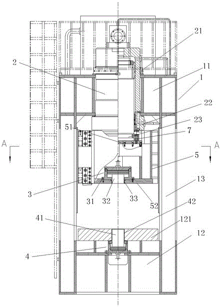
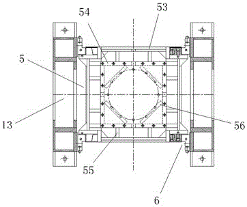
[0017] like figure 1 and figure 2 As shown, the present invention comprises fuselage 1, main oil cylinder 2, counter pressure cylinder 3, ring gear cylinder 4 and slide block 5, and fuselage 1 is the closed fuselage of frame structure, comprises upper beam 11, lower workbench 12 and The side arms 13 located on both sides of the upper beam 11 and the lower workbench 12, such a structure makes the radius λ≤1 / 20000 of the fuselage 1 the height of the fuselage, which is much smaller than the radius λ≤1 of the existing fine blanking hydraulic press The height of the fuselage is / 6000, and the rigidity of the fuselage 1 is more than 3 times that of the existing fuselage, which ensures the running accuracy of the slider 5, thereby greatly improving the quality of the precision blanking parts. The ring gear cylinder 4 is arranged in the lower workbench 12, the upper end of t...


PUM


Abstract

The invention discloses a hydraulic machine for fine blanking of sheet metal. The hydraulic machine comprises a machine body, a main oil cylinder, a back-pressure cylinder, a gear ring cylinder and a sliding block, wherein the gear ring cylinder is arranged in a lower workbench of the machine body; the upper end of a piston rod of the gear ring cylinder is supported in a lower guide sleeve; the lower guide sleeve is fixed in a central hole of a workbench plate; the main oil cylinder perpendicularly downward penetrates through an upper cross beam and is fixed at the center of the upper cross beam; the head part of a piston rod of the main oil cylinder is fixed on the upper side of the sliding block; the back-pressure cylinder is positioned in the sliding block; the lower side of the back-pressure cylinder is fixed inside the lower part of the sliding block; the lower end of a piston rod of the back-pressure cylinder is supported in an upper guide sleeve; and the upper guide sleeve is fixed in a central hole of the lower side of the sliding block. The hydraulic machine disclosed by the invention is simple in structure and has the advantages that the defect of desynchrony of a multi-cylinder system is overcome, the rigidity of the machine body is greatly improved, the running precision of the sliding block is guaranteed, and the requirement for utilization of a high-precision fine blanking die is met; meanwhile, the forming rate of blanked parts is improved and the material waste cost is reduced; and the flatness, the surface smoothness and the size precision of the blanked parts are improved.

Description

technical field [0001] The invention relates to a hydraulic press with a vertical fuselage, in particular to a precision blanking hydraulic press capable of significantly improving the quality of blanking parts, and belongs to the technical field of forging machinery. Background technique [0002] Use a precision blanking press and a special fine blanking die to fine blank the sheet, so that the blanking area of ​​the sheet is in a special three-dimensional compressive stress state to obtain precise dimensions, flat surfaces and smooth shear surfaces, without Re-cutting is required, which can improve the processing efficiency and reduce the processing cost of parts. The advantages of fine blanking parts make them widely used in the body shell of automobiles and motorcycles and the stamping parts of computers. For fine blanking parts, the fine punching die installed on the three-action press must be used to press the plate first and then cut, so as to obtain high-quality f...

Claims


Application Information

Patent Timeline
IPC IPC(8): B30B1/32B30B15/04B30B15/00B21D28/02
CPCB30B1/32B21D28/02B30B15/00B30B15/04
Inventor 陆召庭
Owner WORLD PRECISE MACHINERY CO LTD CHINA
Learn More