
Dust collector motor

A technology for vacuum cleaners and components, applied in the manufacture of motor generators, electric components, electrical components, etc., can solve the problems of sparks generated by carbon brushes and commutators, and the reduction of motor power, and achieve superior performance, long life, and low friction. Effect

Inactive Publication Date: 2016-11-16
宁波市镇海净典环境治理服务有限公司
View PDF0 Cites 3 Cited by
  • Summary
  • Abstract
  • Description
  • Claims
  • Application Information

AI Technical Summary

Problems solved by technology

[0002] With the development of the times, people's quality of life is getting higher and higher, and vacuum cleaners are also widely used in people's lives. At present, many vacuum cleaners use DC motors, and DC motors have organic shells, permanent magnets, and carbon brushes. , the rotor and the rotor winding, when the motor is running, the rotor winding continuously switches the current due to the high-speed friction between the carbon brush and the commutator, resulting in sparks between the carbon brush and the commutator. The motor has the following disadvantages: 1. This kind of motor cannot be used as power in combustible and explosive situations; 2. When this kind of motor is working, sparks are generated between the two contacts, resulting in carbon deposits, which cause a certain amount of friction between the circuits. The resistance of the motor will cause the power of the motor to drop

Method used


Image

  • Dust collector motor
  • Dust collector motor

Examples


specific Embodiment approach

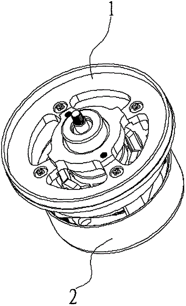
[0014] A vacuum cleaner motor, the motor includes a housing, a stator assembly and a rotor assembly, the housing includes a front end cover 1 and a rear end cover 2; the rotor assembly includes a rotor shaft 6, permanent magnets 8, fixed Magnetic steel sleeve 9, rotor punch 7 and bearing 3, the two ends of described rotor shaft 6 are provided with bearing 3 respectively, the middle part of described rotor shaft 6 is provided with rotor punch 7, described rotor punch 7 The side of the rotor is bonded with permanent magnets 8, and the two ends of the rotor punch 7 are provided with fixed magnet sleeves 9; the stator assembly includes a stator core 4, a stator winding 5 and a Hall induction plate 10, the The stator winding 5 is wound on the stator core 4, the Hall induction board 10 is fixedly installed on the inner wall of the rear end cover 2, and the Hall induction board 10 includes a substrate and a semiconductor induction assembly; The stator assembly and the rotor assembly ...


PUM


Abstract

The invention relates to a motor, especially a vacuum cleaner motor. The motor includes a housing, a stator assembly and a rotor assembly. The housing includes a front end cover and a rear end cover, and the front end cover and the rear end cover are fixed by screwing; The rotor assembly includes the rotor shaft, permanent magnetic steel, fixed magnetic steel sleeve, rotor punch and bearings. The two ends of the rotor shaft are equipped with bearings, the middle of the rotor shaft is equipped with rotor punch, and the side of the rotor punch is bonded with permanent Magnetic steel, fixed magnetic steel sleeves are provided at both ends of the rotor punching sheet; the stator assembly includes stator core, stator winding and Hall induction plate, the stator winding is wound on the stator iron core, and the Hall induction plate is fixedly installed at the rear end On the inner wall of the cover; the stator assembly and the rotor assembly are installed in the housing; the invention not only has a good heat dissipation effect, but also has no sparks and no ablation during the working process, can work in relatively harsh and dangerous environments, and has small friction and Low noise, long life, low energy consumption, performance is superior to ordinary DC motors.

Description

technical field [0001] The invention relates to a motor, in particular to a vacuum cleaner motor. Background technique [0002] With the development of the times, people's quality of life is getting higher and higher, and vacuum cleaners are also widely used in people's lives. At present, many vacuum cleaners use DC motors, and DC motors have organic shells, permanent magnets, and carbon brushes. , the rotor and the rotor winding, when the motor is running, the rotor winding continuously switches the current due to the high-speed friction between the carbon brush and the commutator, resulting in sparks between the carbon brush and the commutator. The motor has the following disadvantages: 1. This kind of motor cannot be used as power in combustible and explosive situations; 2. When this kind of motor is working, sparks are generated between the two contacts, resulting in carbon deposits, which cause a certain amount of friction between the circuits. The resistance of the mo...

Claims


Application Information

Patent Timeline
Patent Type & Authority Applications(China)
IPC IPC(8): H02K1/27H02K11/215H02K5/04H02K5/20H02K15/00
CPCH02K1/2706H02K5/04H02K5/20H02K15/00
Inventor 吴建云
Owner 宁波市镇海净典环境治理服务有限公司
Learn More