
Closed-loop steel sintered red ore cooling device and process method thereof

A closed-circuit circulation and cooling device technology, applied in the field of thermodynamics, can solve problems such as belt transportation and ore screening adverse effects, sinter quality cannot be guaranteed, and sintering machine leakage rate is high, so as to reduce power, save electricity, and occupy an area The effect of less area

Active Publication Date: 2016-11-16
BEIJING RUIDA HONGXIN TECH CO LTD
View PDF6 Cites 8 Cited by
  • Summary
  • Abstract
  • Description
  • Claims
  • Application Information

AI Technical Summary

Problems solved by technology

[0003] The structure of the walking sintering machine consists of two parts: a sintering section and a cooling section. The cooling time is short, the cooling effect is not good, and even red ore is produced, so that the quality of the sintering ore cannot be guaranteed, and it has adverse effects on belt transportation and ore screening. At the same time, affected by the sealing structure of the step-by-step sintering machine, the air leakage rate of the sintering machine is very high, which can reach more than 50%, which requires a large amount of air for cooling, consumes a lot of energy, and is difficult to recycle
[0004] Belt-type sintering machines are generally cooled by ring coolers. Ring coolers are also affected by the sealing structure. The air leakage rate of the sintering machine is over 50%, which requires a large amount of air for cooling, consumes a lot of energy, and causes recycling. difficult question
[0005] At present, the waste heat recovery of sintering machines in my country's iron and steel industry can only reach 10-18 degrees per ton of ore, and the heat extraction is low and cannot be fully utilized.
At the same time, a large amount of smoke is discharged outside, which produces a large amount of carbon emissions and pollutes the environment

Method used


Image

  • Closed-loop steel sintered red ore cooling device and process method thereof

Examples


Embodiment Construction

[0030] The present invention will be described in detail below in conjunction with the accompanying drawings and specific embodiments.

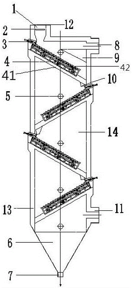
[0031] A closed-circuit circulation iron and steel sintered red ore cooling device, comprising a device body 13, a heat exchange chamber 14 arranged in the device body, a feed inlet 1 arranged at the upper end of the device body 13, and a uniformly distributed Device 2 and the outlet 7 located at the lower end of the body;

[0032] And the cold air outlet 8 provided on the upper end side wall of the device body and the cold air inlet 11 arranged on the lower end side wall of the device body communicated with the heat exchange chamber;

[0033] And the thermostat 9 arranged on the device body, the thermostat 9 communicates with the cold air outlet 8;

[0034] And at least one fire grate 4 that is movably installed in the heat exchange chamber 14, each fire grate 4 is inclined downward with the heat exchange chamber and is arranged in parallel...


PUM


Abstract

The invention discloses a closed-loop steel sintered red ore cooling device. The device comprises a device body, a heat exchange cavity arranged in the device body, a feeding inlet formed in the upper end of the device body, a uniform distributor arranged at the lower end of the feeding inlet, a discharging outlet formed in the lower end of the body, a uniform temperature device and at least one fire grate. The uniform temperature device is arranged on the device body and communicates with a cold air outlet. The at least one fire grate is movably installed in the heat exchange cavity. Each fire grate and the heat exchange cavity form an obliquely-downward angle, and the fire grates are parallel to each other. A pushing device is arranged at the front end of each fire grate. A hopper is arranged at the tail end of each fire grate. The device replaces a cooling section of an original sintering machine or a ring cooling machine. Compared with an original cooling mode, the device is high in yield, good in quality and low in energy consumption. Compared with the original cooling mode, the yield of a marching type sintering machine can be increased by 30%-40%, zone firing is increased by 5%-10%, and energy consumption only accounts for about 50% of the original cooling mode.

Description

technical field [0001] The invention belongs to the field of thermodynamics, and in particular relates to a closed-circuit circulation iron and steel sintered red ore cooling device and a process method thereof. Background technique [0002] At present, there are mainly two types of sintering machines in my country's iron and steel industry, one is a step-by-step sintering machine, and the other is a belt-type sintering machine. [0003] The structure of the walking sintering machine consists of two parts: a sintering section and a cooling section. The cooling time is short, the cooling effect is not good, and even red ore is produced, so that the quality of the sintering ore cannot be guaranteed, and it has adverse effects on belt transportation and ore screening. At the same time, affected by the sealing structure of the step-by-step sintering machine, the air leakage rate of the sintering machine is very high, which can reach more than 50%, which requires a large amount o...

Claims


Application Information

Patent Timeline
IPC IPC(8): F27D15/02
CPCF27D15/02
Inventor 洪光信渠秀红张惠东杨献琳王振杰
Owner BEIJING RUIDA HONGXIN TECH CO LTD
Learn More