Spiral drilling machine

A technology of auger drilling rigs and hexagonal bolts, which is applied in the direction of rotary drilling rigs, rotary drilling, mechanical equipment, etc. It can solve the problems of inconvenient installation and maintenance, large volume and heavy weight of large displacement motors, and achieve reliable structure, The effect of easy maintenance

Active Publication Date: 2016-11-16
张家港保税区永大机械有限公司
View PDF9 Cites 2 Cited by
  • Summary
  • Abstract
  • Description
  • Claims
  • Application Information

AI Technical Summary

Problems solved by technology

[0002] At present, in the construction of general construction projects, it is often necessary to drill holes in some drilling equipment. Usually, an auger drill is used to provide kinetic energy to the drill bit for construction. The traditional auger drill is usually powered by a motor, and the power is transmitted to the drive shaft by means of transmission gears. Drive the drill bit to operate. Although the above structure can meet the basic work needs, for some relatively hard geology, a large motor is needed to generate enough power. The large displacement motor is large in size and heavy in weight, which is inconvenient for installation and maintenance. How to increase power without sacrificing volume and quality is an important technical problem to be solved by those skilled in the art

Method used


Image

  • Spiral drilling machine
  • Spiral drilling machine
  • Spiral drilling machine

Examples


Embodiment 1

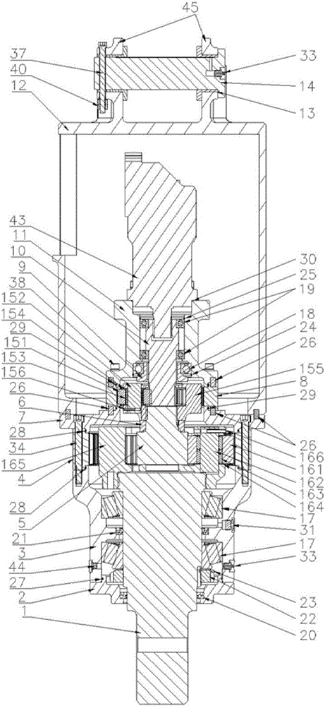
[0024] like figure 1 As shown, the present invention provides an auger drilling machine, including an oil seal cover 2, above which a bearing seat 3, a secondary rotary assembly 16, a flange 7 and a motor housing 12 are sequentially assembled; Positioning pins 26 are also provided at the joints between the flange 7 and the motor housing 12; the flange 7 and the motor housing 12 are connected and fixed by hexagon socket bolts 336; the oil seal cover 2 and the bearing The inner side of the seat 3 is assembled with the output shaft 1, and the oil seal cover 2 and the bearing seat 3 are fixed by hexagon socket bolts 639; the junction of the oil seal cover 2 and the bearing seat 3 is provided with an O-ring One 27; the bearing seat 3 is provided with plug one 31, plug two 44 and grease fitting 33; one end of the output shaft 1 passes through the bearing seat 3 and the oil seal cover 2 for external load, and the other One end engages with the secondary slewing assembly 16;

[0025...


PUM


Abstract

The invention discloses a spiral drilling machine which comprises an oil seal cover. A bearing seat, a secondary rotation assembly, a flange and a motor outer shell are sequentially connected above the oil seal cover. An output shaft is connected to the inner sides of the oil seal cover and the bearing seat. One end of the output shaft penetrates through the bearing seat and the oil seal cover and is used for being externally connected with a load. The other end of the output shaft is engaged with the secondary rotation assembly. A secondary sun lgear in the secondary rotation assembly penetrates through the flange and is connected with a primary rotation assembly in an engaged mode. A primary sun gear shaft in the primary rotation assembly is connected with a hydraulic motor installed on a motor base in an engaged mode. The primary rotation assembly, the motor base and the hydraulic motor are all connected inside the motor outer shell. The spiral drilling machine has the beneficial effects that the spiral drilling machine can be used for mounting various drill bits, and through the primary rotation assembly and the secondary rotation assembly, large torque output can be achieved when a small-displacement hydraulic motor is adopted; and in addition, the primary rotation assembly and the secondary rotation assembly are connected in an engaged mode, a split structure is adopted, the structure is reliable, and maintenance is convenient.

Description

technical field [0001] The invention relates to an auger drilling device, which is used to drive a drill bit for construction in various operations such as piling. Background technique [0002] At present, in the construction of general construction projects, it is often necessary to drill holes in some drilling equipment. Usually, an auger drill is used to provide kinetic energy to the drill bit for construction. The traditional auger drill is usually powered by a motor, and the power is transmitted to the drive shaft by means of transmission gears. Drive the drill bit to operate. Although the above structure can meet the basic work needs, for some relatively hard geology, a large motor is needed to generate enough power. The large displacement motor is large in size and heavy in weight, which is inconvenient for installation and maintenance. How to increase power without sacrificing volume and quality is an important technical problem that those skilled in the art need to ...

Claims


Application Information

Patent Timeline
Patent Type & Authority Applications(China)
IPC IPC(8): F16H1/36F16H1/32E21B3/02
CPCE21B3/02F16H1/32F16H1/36
Inventor 方欣骏
Owner 张家港保税区永大机械有限公司
Why Eureka
Try Eureka