Mold insert core monitoring system, mold system and using method of mold system

A monitoring system and mold technology, which is applied in the field of injection molds, can solve problems such as molding risks, increase production costs, and compression molding, so as to reduce the frequency of abnormalities, save mold repair costs, and ensure normal shipments

Inactive Publication Date: 2016-11-16
GOERTEK INC
View PDF7 Cites 0 Cited by
  • Summary
  • Abstract
  • Description
  • Claims
  • Application Information

AI Technical Summary

Problems solved by technology

[0003] At present, the inserts used in the production site are relatively large in combination with the structural characteristics of the product. When installing the inserts, the inserts need to be installed manually. At the same time, it is necessary to visually observe whether the inserts are placed in place. Once due to the negligent operation of the staff, the improper placement of the insert is not recognized in time, and there will be a risk of compression molding after the mold is closed.
[0004] In addition, manual placement of inserts and manual sliding doors not only fail to meet the mass production of the product, but also cause fatigue to the operator; using visual observation to judge the placement of inserts cannot fundamentally monitor the mold, This is not only complicated to operate, low in efficiency, time-consuming and labor-intensive, but also causes mold compression during the operation process, resulting in unnecessary mold repair costs and increased production costs.

Method used


Image

  • Mold insert core monitoring system, mold system and using method of mold system
  • Mold insert core monitoring system, mold system and using method of mold system
  • Mold insert core monitoring system, mold system and using method of mold system

Examples


Embodiment Construction

[0031] In order to make the object, technical solution and advantages of the present invention clearer, the present invention will be further described in detail below in conjunction with the accompanying drawings and embodiments. It should be understood that the specific embodiments described here are only used to explain the present invention, not to limit the present invention.

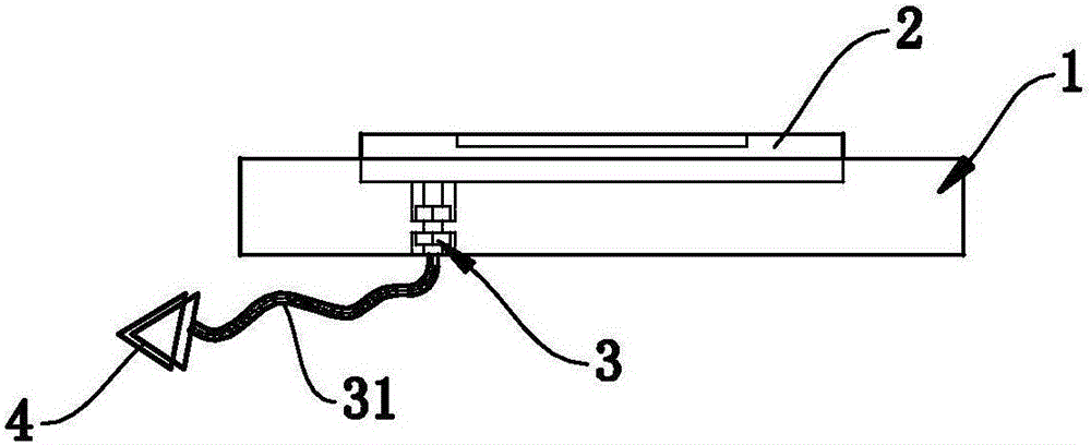
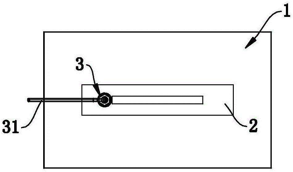
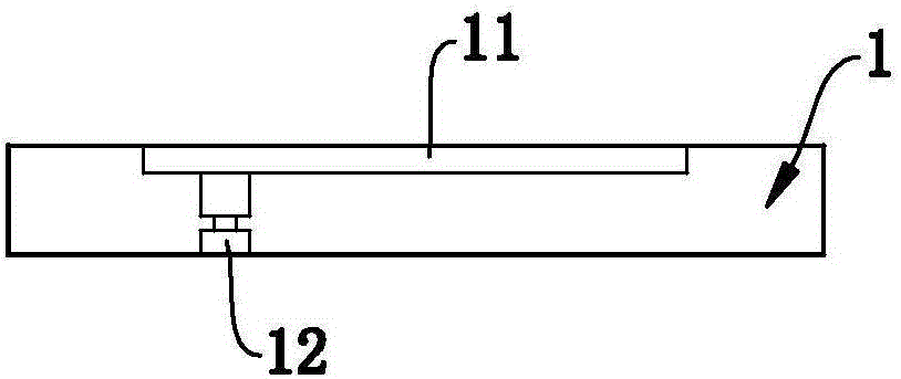
[0032] Such as Figure 1 to Figure 3 Commonly shown, a mold entry monitoring system includes a template 1, preferably, the template 1 is a mother template, the first side of the template 1 is detachably installed with the entry 2, and the second side of the template 1 is provided with a detection entry The limit switch 3 of the sub-2, the limit switch 3 is set corresponding to the sub-2, the limit switch 3 is electrically connected to the control system of the mold (not shown in the figure), the limit switch 3 is also connected to a signal display device, in this implementation For example, prefer...


PUM


Abstract

The invention discloses a mold insert core monitoring system and belongs to the technical field of injection molds. The mold insert core monitoring system comprises a mold plate. An insert core is installed on the first side of the mold plate in a separable mode. A limit switch used for detecting the insert core is arranged on the second side of the mold plate. The limit switch corresponds to the insert core and is electrically connected with a control system of a mold. The limit switch is also connected with a signal display device. The invention further discloses a mold system comprising the mold insert core monitoring system. The invention further discloses a using method of the mold system. The mold system is adopted by the using method. The using method of the mold system comprises the step of installing the insert core on a manipulator, the step of installing the insert core on the mold plate, and the step of mold assembly. By the adoption of the mold insert core monitoring system, the mold system and the using method of the mold system, the installation condition of the insert core can be effectively monitored, the mold is well protected, and unnecessary mold repairing cost is reduced; and the anomaly frequency of the mold is reduced, the stability of product quality is improved, the working efficiency is improved, and normal shipment of products is guaranteed.

Description

technical field [0001] The invention belongs to the technical field of injection molds, and in particular relates to a mold entry monitoring system, a mold system including the above mold entry monitoring system, and a method for using the mold system. Background technique [0002] During the injection molding process of the product, because the mold structure cannot meet the special product structure molding characteristics, it is necessary to process a detachable device on the mold according to the product structure design, that is, the insert. For example, in a complex cavity, there are bulges or deep depressions, which are difficult to cut directly, so it is usually designed as an insert; or in a multi-cavity mold, the entire finished product can be designed as an insert. This process not only saves man-hours, but also facilitates damage replacement or finished product changes. The insert is divided into a male mold insert and a female mold insert. A hole is cut on the ...

Claims


Application Information

Patent Timeline
Patent Type & Authority Applications(China)
IPC IPC(8): B29C45/80B29C45/84B29C45/17B29C33/30
CPCB29C45/1742B29C45/80B29C45/84B29C2945/76732
Inventor 于吉双马立平
Owner GOERTEK INC
Why Eureka
Try Eureka