
Comprehensive control method for pressure position of hot continuous rolling rolled side guide plate

A comprehensive control and pressure control technology, applied in tension/pressure control, rolling mill control devices, metal rolling, etc., can solve the problems of short service life of the side guide plate, wear of the coiling side guide plate, scratches on the edge of the strip, etc. Achieve the effect of improving the stability of production operation, shortening the replacement cycle and reducing downtime

Active Publication Date: 2018-10-30
武汉钢铁有限公司
View PDF7 Cites 8 Cited by
  • Summary
  • Abstract
  • Description
  • Claims
  • Application Information

AI Technical Summary

Problems solved by technology

[0003] This control method will cause partial wear of the take-up side guide plate. Once the wear exceeds 10 mm, the take-up side guide plate must be replaced immediately, resulting in a short service life of the side guide plate, frequent equipment replacement, and high quality risks. The uneven wear of the guide plate causes quality problems such as scratches, cracks, edge damage, and abnormal coil shape on the edge of the strip. At the same time, it has a major impact on the surface quality of the hot-rolled strip. In severe cases, even scrap steel occurs
The solution to such problems can only be achieved by stopping the machine to replace the coiling side guide, which not only affects production efficiency, but also increases safety risks

Method used

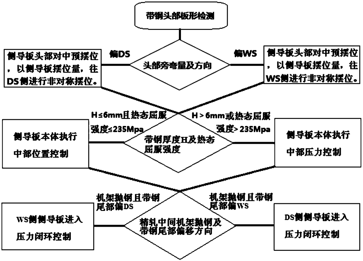

Image

  • Comprehensive control method for pressure position of hot continuous rolling rolled side guide plate
  • Comprehensive control method for pressure position of hot continuous rolling rolled side guide plate
  • Comprehensive control method for pressure position of hot continuous rolling rolled side guide plate

Examples


Embodiment 1

[0081] In the embodiment of the present invention, a method for comprehensively controlling the pressure position of the coiling side guide plate of hot continuous rolling is applied to the production of cold-rolled plain steel with a finished product size of 3.5*1550mm (the yield strength in the hot state is about 150Mpa), and includes the following steps:

[0082] (1) Strip head shape detection:

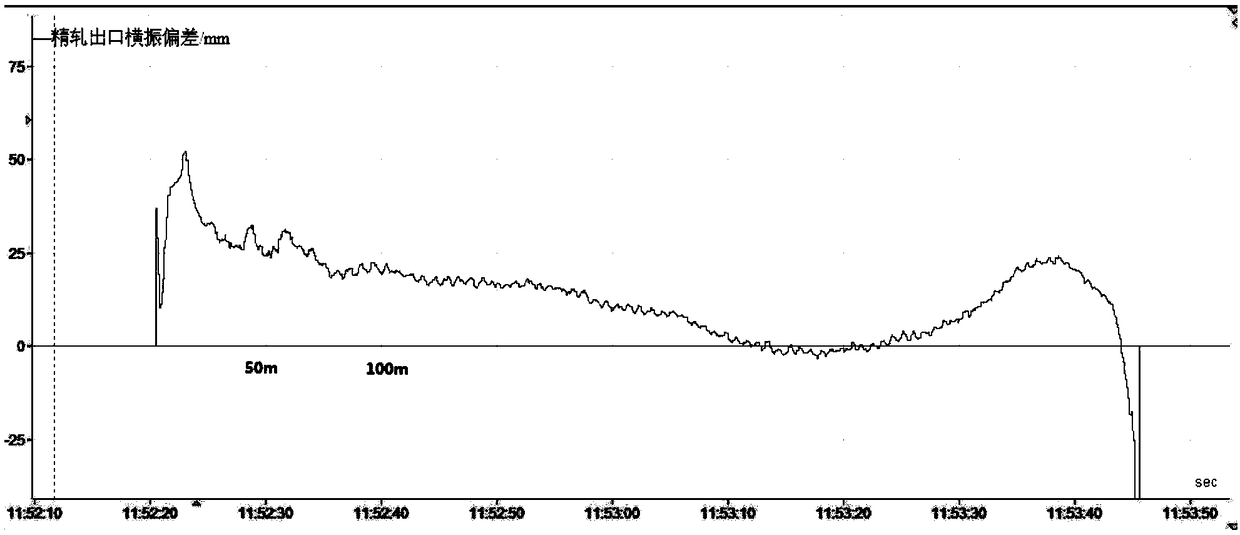
[0083] Detect the side bending of the strip head and the offset value of the strip body at the exit of the finishing mill. Specifically, the transverse vibration curve of the exit of the strip is obtained by using the exit width gauge of the exit of the strip. The exit of the strip of this type is The lateral vibration curve is as figure 2 shown;

[0084] According to the transverse vibration curve at the exit of finishing rolling, the maximum value Dev of the transverse vibration within 50m of the strip head can be calculated. max and the minimum Dev min , and within the range...

Embodiment 2

[0111] In an embodiment of the present invention, a method for comprehensively controlling the pressure position of the coiling side guide plate of hot continuous rolling is applied to the production of automobile frame steel with a finished product size of 8*1500mm (the yield strength in the hot state is about 355Mpa), and includes the following steps:

[0112] (1) Strip head shape detection:

[0113] The exit transverse vibration curve of this type of strip steel is as follows: Figure 4 As shown, according to the exit transverse vibration curve of the finishing rolling, the maximum value Dev of the transverse vibration within 50m of the strip head can be calculated max and the minimum Dev min , and within the range of 50m to 100m of strip steel (corresponding Figure 4 From 12:08:35 to 12:08:55) mean value of horizontal vibration Dev ave ; take Dev max -Dev ave with Dev min -Dev ave The larger difference in the middle value is taken as the side bending amount of the ...

Embodiment 3

[0131] In an embodiment of the present invention, a method for comprehensively controlling the pressure position of the coiling side guide plate in hot continuous rolling is applied to the production of wheel steel with a finished product size of 4*1300mm (the yield strength in the hot state is about 500Mpa), and includes the following steps:

[0132] (1) Strip head shape detection:

[0133] The exit transverse vibration curve of this type of strip steel is as follows: Image 6 As shown, according to the exit transverse vibration curve of the finishing rolling, the maximum value Dev of the transverse vibration within 50m of the strip head can be calculated max and the minimum Dev min , and within the range of 50m to 100m of strip steel (corresponding Image 6 From 11:58:40 to 11:58:53) the average value of the horizontal vibration Dev ave ; take Dev max -Dev ave with Dev min -Dev ave The larger difference in the middle value is taken as the side bending amount of the st...


PUM

PropertyMeasurementUnit
Thicknessaaaaaaaaaa
Thicknessaaaaaaaaaa
Thicknessaaaaaaaaaa

Abstract

The invention discloses a comprehensive control method for the pressure position of a hot continuous rolling rolled side guide plate. At the head of all-variety strip steel, side guide plate head alignment pre-positioning control is conducted according to the finish rolling incoming material plate shape and the transverse vibration situation; for thin-specification plain carbon steel, the cold state width value is calculated at the corresponding rolling target temperature through an instrument, side guide plate middle position control is achieved; for thick-specification high-strength steel, side guide plate middle pressure closed-loop control is achieved; and at the tail of the all-variety strip steel, automatic side guide plate tail pressure closed-loop control is achieved according to the strip steel tail deflection direction. In the whole rolling period, the actual positions of the head and the tail of the strip steel are tracked in real time, and accordingly corresponding actionsare executed. Since the comprehensive control method is input, the on-machine service time of a rolled side guide plate is seven days; the cold-rolled raw material edge breaking material return rate is reduced to 0.46%, the thin-specification plain carbon steel roll head tower-form maximum value is reduced to 30 mm, and steel roll middle maximum roll-shaped sawteeth are reduced to 2 mm; and the abnormal roll shape occurrence rate is reduced to 1.52%.

Description

technical field [0001] This application relates to the technical field of coiling of coilers, in particular to a method for comprehensively controlling the pressure position of a coiling side guide plate, which is applied to a hot continuous rolling production line and can be extended to the coiling area of ​​other hot continuous rolling production lines. Background technique [0002] As the quality requirements of cold-rolled automobile outer plates and hot-rolled pickled steel raw materials continue to increase, the processing methods and uses of users continue to improve. In order to ensure the coil shape quality of hot continuous rolled steel coils, the traditional coiling side guide plate passing control of hot continuous strip steel is realized through the detection of the position of the strip head and the closed-loop control of the coiling side guide plate’s full pressure. [0003] This control method will cause partial wear of the take-up side guide plate. Once the ...

Claims


Application Information

Patent Timeline
IPC IPC(8): B21B37/68B21B37/48
CPCB21B37/48B21B37/68
Inventor 徐浩赵闻刘炜程礼
Owner 武汉钢铁有限公司
Learn More