Exchange table of fiber laser cutting machine

A fiber laser and switching table technology, applied in the field of switching tables, can solve the problems of low precision, poor work continuity, intermittent interruption of processing work, etc., and achieve the effects of reasonable mechanical structure design, guaranteed cutting quality, and improved synchronization.

Inactive Publication Date: 2016-11-16
广州市粤雕自动化设备有限公司
View PDF6 Cites 5 Cited by
  • Summary
  • Abstract
  • Description
  • Claims
  • Application Information

AI Technical Summary

Problems solved by technology

[0003] The optical fiber laser processing equipment in the prior art generally only has one laser cutting area, that is, after cutting the corresponding incoming workpiece, it is necessary to unload the processed workpiece, and then load a new incoming workpiece to continue cutting, so First, even if the processing work is interrupted at intervals, the work continuity is poor, the production speed is slow, the production efficiency is low, and the processing cycle is long, which also makes various costs higher.
There are also some optical fiber laser processing equipment that exchange worktables for laser cutting. This kind of optical fiber laser processing equipment uses hydraulic pressure for lifting and lowering during the exchange process. The hydraulic drive has the risk of pressure release, and the use is unstable. low

Method used


Image

  • Exchange table of fiber laser cutting machine
  • Exchange table of fiber laser cutting machine
  • Exchange table of fiber laser cutting machine

Examples


Embodiment Construction

[0018] Now the present invention is further described in conjunction with description of drawings and embodiments:

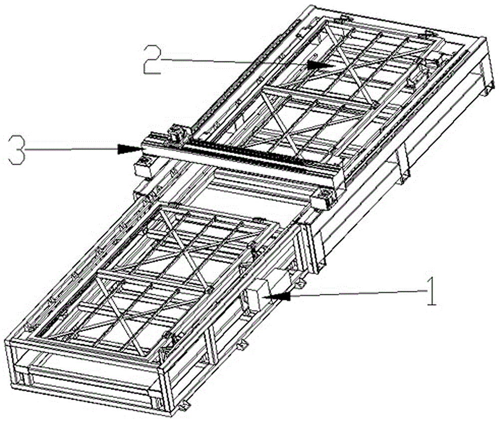
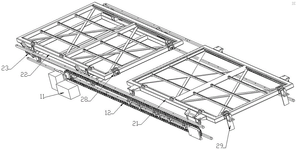
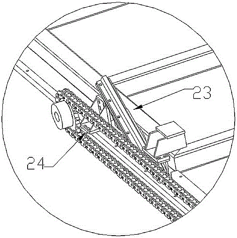
[0019] refer to figure 1 and figure 2 , an exchange platform for a fiber laser cutting machine, including a drive module 1 on the main bed, a workbench 2 and a laser module 3, wherein: the drive module includes a drive motor 11 and a drive chain 12, both of which are arranged on the main bed On one side, the drive chain 12 is divided into an upper chain and a lower chain with two left and right gears as endpoints, and the workbench is staggered left and right and divided into an upper workbench 21 and a lower workbench 22, and the lower workbench 22 is provided with Sliding support frame 23, described and one side of upper workbench 21 and lower workbench 22 are all provided with limit upper pulley 28, one side of described main bed is provided with limit stop 29, and described limit stop 29 limits the limit sliding position of the upper table 21 and the lowe...


PUM


Abstract

The invention discloses an exchange table of a fiber laser cutting machine. The exchange table comprises a driving module, a worktable and a laser module, all of which are arranged on a main bed body. The driving module comprises a driving motor and a driving chain which are arranged on one side of the main bed body. The driving chain is divided into an upper chain body and a lower chain body with a left gear and a right gear as the end points. The worktable is divided into an upper worktable body and a lower worktable body in a left-right staggered manner. An upper sliding supporting frame is arranged below the lower worktable body. The upper sliding supporting frame is connected into a first chain joint of the lower chain body through a first right-angle connecting piece and is fixed. Upper limiting pulleys are arranged on one side of the lower worktable body. An oblique guide rail is arranged at the position, corresponding to the part below a sliding wheel of the lower worktable body, of the upper sliding supporting frame. According to the exchange table of the fiber laser cutting machine, the oblique guide rail is adopted to be matched with a purely-mechanical structure of the sliding wheel in the exchange process, the problem that pressure releasing and control are not stable in traditional hydraulic exchange is solved, higher stability and the lower failure rate are provided, cost is low, and maintenance is convenient.

Description

technical field [0001] The invention relates to the field of laser cutting machines, in particular to an exchange table of an optical fiber laser cutting machine. Background technique [0002] In the machinery industry, thin metal sheets, stainless steel sheets, aluminum sheets, carbon steel sheets, traditional flame cutting, and plasma cutting are often cut, making products prone to burrs, and there are certain technical defects in processing accuracy and cutting quality. Fiber laser is a new type of fiber laser newly developed in the world. It outputs high-energy-density laser beams and gathers them on the surface of the workpiece, so that the area irradiated by the ultra-fine focus spot on the workpiece is instantly melted and gasified, and the spot is moved by the numerical control mechanical system. Automatic cutting is realized by irradiating the position, with high speed and high precision. For this reason, the present invention provides an optical fiber laser cuttin...

Claims


Application Information

Patent Timeline
Patent Type & Authority Applications(China)
IPC IPC(8): B23K26/38B23K26/70B23K37/00
CPCB23K26/38B23K26/702B23K37/00
Inventor 屈存兵
Owner 广州市粤雕自动化设备有限公司
Why Eureka
Try Eureka