
Internal clamping type chuck

A chuck and chuck-type technology, which is applied in the field of internal chucks for lathes, can solve the problems of scrapped workpieces and offset of processing parts, and achieve the effects of eliminating adverse effects and improving processing reliability and processing efficiency.

Inactive Publication Date: 2016-11-16
中联精工(天津)有限公司
View PDF0 Cites 0 Cited by
  • Summary
  • Abstract
  • Description
  • Claims
  • Application Information

AI Technical Summary

Problems solved by technology

However, the fixed method of clamping on the outer peripheral side often causes the central axis of the inner diameter of the workpiece to deviate from the central axis formed by the clamping part due to the difference in the thickness of the side of the tubular workpiece, so that the workpiece will be in the processing part of the machine tool. Deviation occurs, and even the workpiece is scrapped after processing

Method used


Image

  • Internal clamping type chuck
  • Internal clamping type chuck
  • Internal clamping type chuck

Examples


Embodiment Construction

[0016] The present invention will be further described below in conjunction with the accompanying drawings.

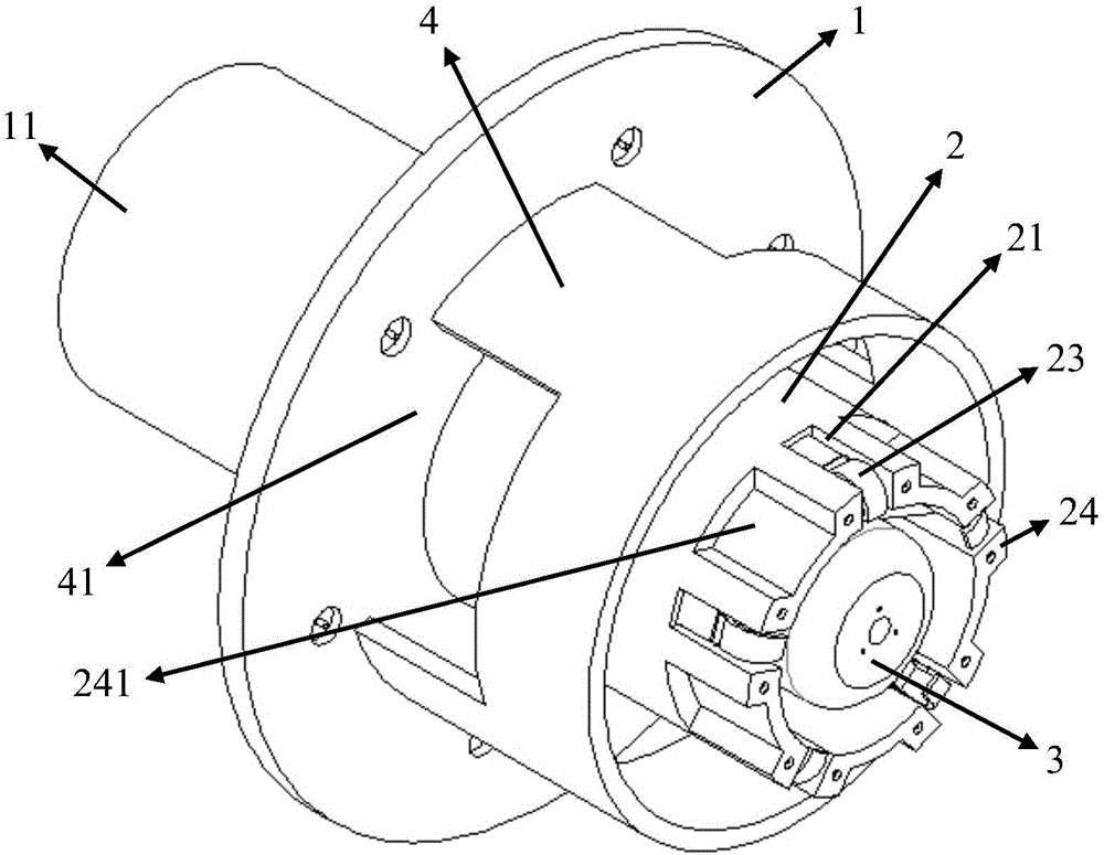
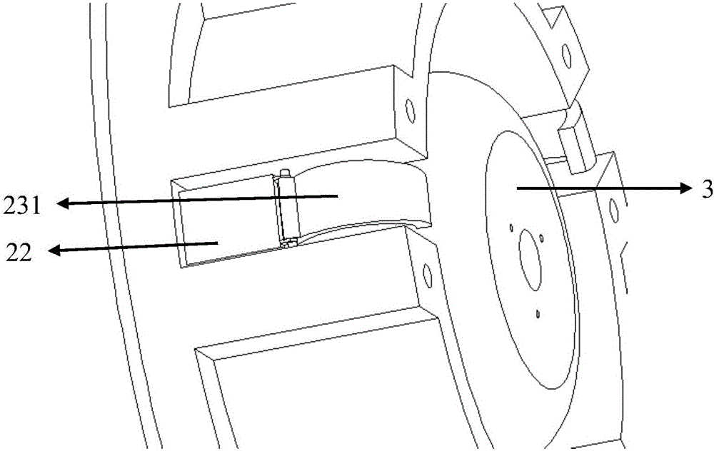
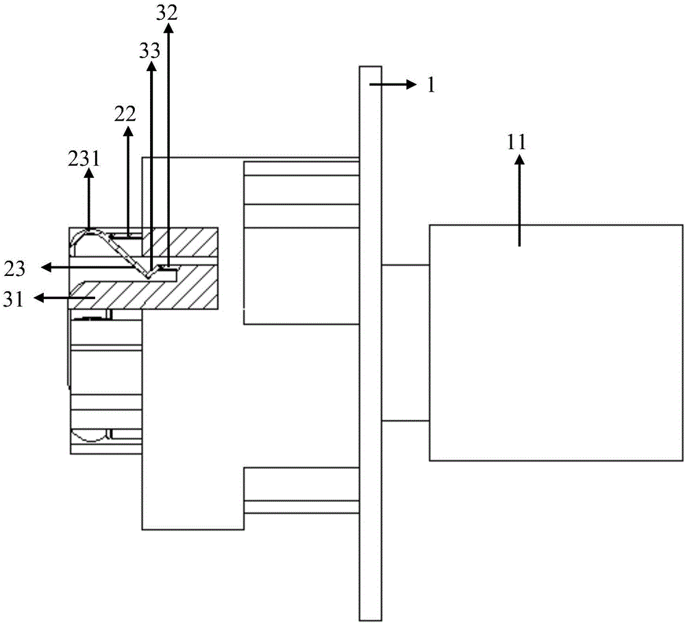
[0017] One embodiment of the structure of the present invention is as Figure 1-3 As shown, it includes a fixed chassis 1 and a clip seat 2 coaxially fixedly connected with it. The end of the clip seat 2 is provided with a number of grooves 21 extending inward along the side wall, and a support wall 22 is provided in the groove 21. , the top of the support wall 22 is hinged with the outer wall of a movable rod 23 near the head 231, the center of the clamp seat 2 is coaxially provided with a telescopic rod 3, and the center of the head of the telescopic rod 3 is a columnar boss 31. A push arm 32 is provided around the head of the telescopic rod 3, and the push arm 32 is connected to the tail of the movable rod 23 through a connecting buckle 33, and the two ends of the connecting buckle 33 are respectively connected to the push arm 32 and movable bar 23 are hinged. The...


PUM


Abstract

The present invention provides an inner clamping chuck, which comprises a coaxially fixedly connected chassis and a clamp seat, and a support wall is arranged at intervals at the end of the clamp seat, and the support wall is hinged to the head of a movable rod, and the clamp A telescopic rod is coaxially arranged in the center of the seat, and the tail of the movable rod is hinged with the connecting buckle and the push arm in turn. The push arm is located around the telescopic rod. The invention can clamp and fix the tubular workpiece from the inside, which solves the processing deviation The phenomenon.

Description

technical field [0001] The invention belongs to the technical field of machine tool equipment design and manufacture, and in particular relates to an internal clamping chuck for a lathe. Background technique [0002] The chuck is one of the commonly used accessories on the machine tool, which is used for stable positioning and clamping of the workpiece to be processed. For tubular workpieces, general chucks clamp and fix the workpiece from the outer peripheral side, and then perform subsequent processing operations on the machine tool. However, the fixing method of clamping on the outer peripheral side often causes the central axis of the inner diameter of the workpiece to deviate from the central axis formed by the clamping part due to the difference in the thickness of the side of the tubular workpiece, so that the processing part of the workpiece during machine tool processing Offset occurs, and even the workpiece is scrapped after processing. Contents of the invention...

Claims


Application Information

Patent Timeline
IPC IPC(8): B23B31/16
CPCB23B31/16
Inventor 张海宽于大宽
Owner 中联精工(天津)有限公司
Learn More